That does look like very practical arrangement - not like the deadly Flyer "Mincer" idea. Now you can concentrate on developing the engine and not worry about the other crap.


BOEING / GoFly contest: Oh, BOEING
Started by
manolis
, Aug 03 2018 05:44
270 replies to this topic
Advertisement
#252

manolis
-
- 940 posts
- Joined: May 03
Member
Posted 05 September 2020 - 03:17
Hello Kelpiecross.
You write:
“That does look like very practical arrangement - not like the deadly Flyer "Mincer" idea. Now you can concentrate on developing the engine and not worry about the other crap.”
The OPRE engine combines a couple of unconventional ideas to offer some advantages over the conventional reciprocating piston engines. Yet it is just an engine.
The Portable Flyer combines several eccentric ideas to make an unconventional transportation means that can change the world. Lightweight (to be wearable), simple (to be reliable), fuel efficient (dozens of times more efficient that the existing JetPack alternatives), with instinctive control (like a bicycle; no need for electronics), capable to hover for hours (for rescue and for surveillance), capable to cruise at speeds barely affordable by the pilot, and affordable for everyone (its cost is lower than the cost of a scooter).
You fear the rotating propellers over the head of the pilot (unless I am wrong this is your basic objection for years now).
The following quote from another forum discussion answers your basic objection:
In this case (PatATi Opposed Piston engine, 800cc, "ATi": Asymmetric Transfer and intake):
the pilot cannot reach the propellers, no matter how hard he will try.
The same engine runnign on gasoline (fuel injection, spark ignition):
In this case (single OPRE Tilting, direct drive of propellers :
the frame, which is shown more clearly here:
is not allowing pilot's arm / hands to reach the lower propeller, no matter how hard he tries.
In this case (Portable Flyer with the two OPRE tilting engines leaning backwards :
the pilot cannot reach (with his limbs) the propellers.
Can't a motorcycle or bicycle rider put his hand / fingers in the space wherein the spokes of the rear wheel spin? But he has to put a lot of effort to do this, and it is supposed he is not completely idiot.
While all the previous are significant for the safety of pilot's limbs, when he flies the top risk (the lethal danger) is to lose power (or control) and fall heating the ground.
This is why a pair of independent propulsion units:
is so important.
Quote from https://www.pattakon...takonPatTol.htm :
SAFETY
As the Osprey, the Portable Flyer is capable for "vertical take-off / landing (like a helicopter), and for high-speed long-distance high-mileage flights (like an airplane).
The malfunction of the one propulsion unit (due, for instance, to an engine failure, or to a rotor breakdown, or to a broken tooth-belt etc) is not fatal because the other (completely independent) propulsion unit, ALONE, is capable for the safe landing of the Portable Flyer.
In the Osprey V-22 the malfunction / collapse / breakdown of the one rotor may turn out fatal, especially during a vertical take-off or landing.
In comparison, the Portable Flyer with the two OPRE Tilting engines is safer.
The breakdown of a rotor of a propulsion unit is not fatal: the other propulsion unit of the Portable Flyer (comprising an engine and two counter-rotating rotors) enables a safe landing or, if necessary, the flight to the closest safe landing place.
Even in the case wherein both propulsion units fail, or in the case the Portable Flyer runs out of fuel, the Portable Flyer can still, using the rescue parachutes, land safely."
Thanks
Manolis Pattakos
#253
manolis
-
- 940 posts
- Joined: May 03
Member
Posted 14 September 2020 - 06:57
Hello all
MultiQuote from another discussion :
Negative Ground Effect of JetPacks
As Mayman explains (second quote of my last-but-one post), at take-off and landing the ground effect on his JetPack is negative due to recirculation of the exhaust gas in the intake.
Browning’s / gravity JetPack has the same problem:
The problem is worse for Zapata’s JetPack wherein the jet turbines are located under the feet of the pilot. This explains why Zapata needs a special structure (an elevated wire-net) in order to take-off and land:

And why the negative ground effect of the JetPacks is a problem?
Take the case of a vertical landing of Mayman JetPack. At 10ft height the thrust from the jets is substantially stronger than at 1ft height. In order to compensate for the negative ground effect, the pilot has to open properly the throttle; if not, he will have a hard landing.
During landing (i.e. when the most accurate control over the thrust is required), the pilot has to feel (and react instantly) on the reduction (and variations / oscillations) of the available thrust.
If, near the ground, the thrust oscillates due to variations in the percentage of the exhaust gas in the intake, the safety gets at big risk.
On the contrary to the JetPacks, the Portable Flyer (just like the Osprey V22 and the helicopters) has “positive ground effect” (the lift (or thrust) increases as the height reduces), important for soft / easy / controllable landings and take-offs.
****
Pure aerodynamic control
When you sky-dive, your weight is the only thrust force, and your center of gravity is where this thrust force is applied.
By moving your head (or, in general, by varying your body posture) you cannot displace the thrust (i.e. your weight, i.e. the force by which the earth attracts you) offset to your center of gravity.
Being unable to offset the thrust force out of your center of gravity, you are unable for “weight displacement control”.
So, during a sky-dive, by moving your head you control your flight (your “falling flight”) exclusively by “aerodynamic control” (and not by “weight displacement control”).
So, by moving your head at a sky dive, you use pure “aerodynamic control” to steer (to some extent).
Regarding the “extent” of steering:
Using all the parts of your body, the extent of steering (we talk for pure “aerodynamic control”, nothing to do with “weight displacement control”) is more than anyone can ask:
The pilot of the Portable Flyer is, permanently, into a high speed air stream enabling full “Aerodynamic control” (even aerobatics, unless the above video is fake).
The Pilot of the Portable Flyer has also full “weight displacement control” (as the GEN H-4 and more, because in the Portable Flyer the pilot mass is about 80% of the total mass of the flying device:
while in the GEN H-4 (which has not the option of “aerodynamic control”
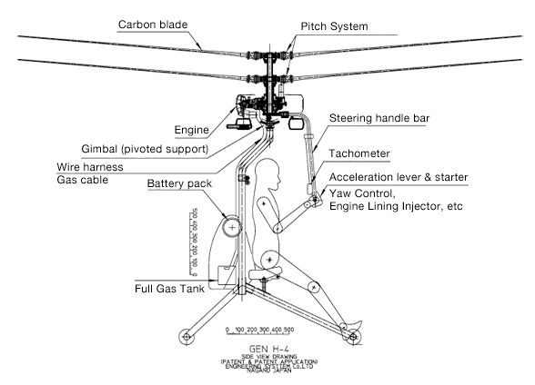
the pilot mass comprises only 50% of the total mass.
The above reply to several suggestions.
The philosophy behind the Portable Flyer is:
to keep the weight the minimum possible,
to simplify the structure using the human body as the basis,
to exploit the available gimbal joints of the human body (the spine is just one of them),
to use the brain, the eyes, the otoliths and the skin as the control system,
to use the muscles and the bones of the pilot as the “servomotors”,
to exploit both “weight displacement” and “aerodynamic” control,
to improve safety by using two completely independent propulsion units,
to focus on simplicity and on affordable cost.
****
Mounting of the propulsion unit
The powerplant of Browning JetPack comprises a central turbine fixed on pilot’s back, and two pairs of turbines fixed on pilot’s arms.
I.e. the powerplant is as fixed on pilot’s body as it gets.
Each pair of turbines has its own “gimbal joint”: it is the shoulder-joint of pilot’s arm whereon the pair of turbines is fixed.
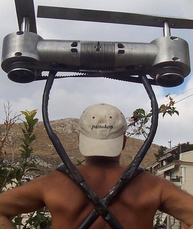
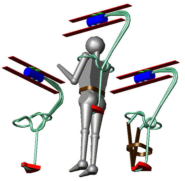
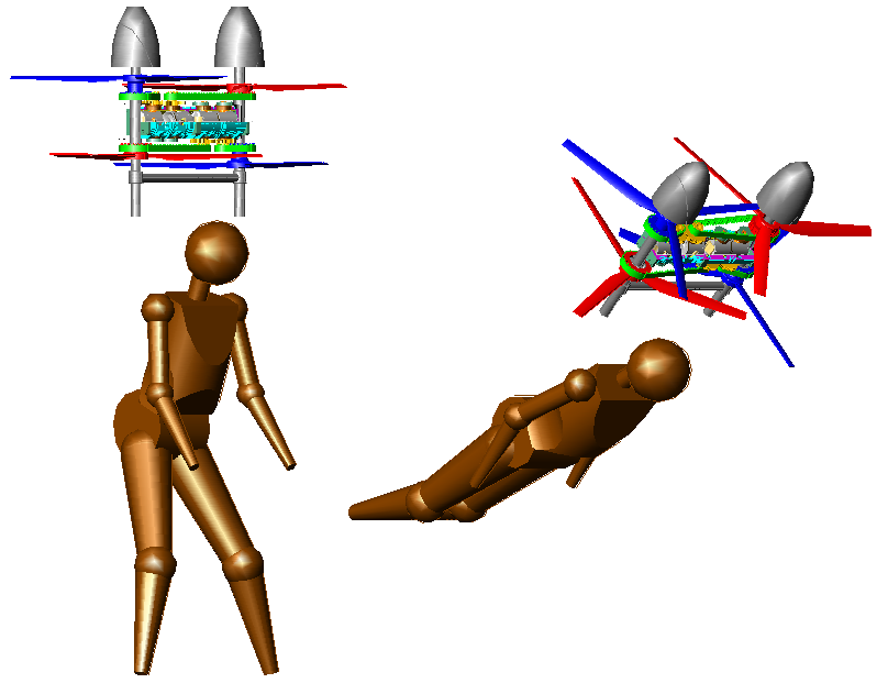
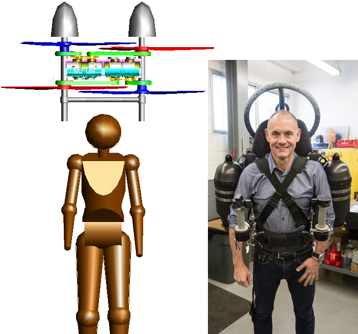
In the Portable Flyer the powerplant is fixed / secured / tighten / fastened on pilot’s back / torso:
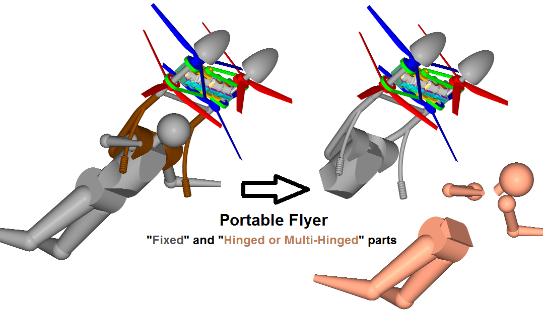
Back, torso and powerplant comprise a (fixed / inflexible) sub-assembly (grey color) shown at right-top in the above drawing.
All the rest parts of pilot’s body (beige color, bottom right), i.e. the hip, the legs, the arms and the head are completely free to move; these free to move parts comprise the big percentage of the human weight.
“Mobility” and Portable Flyer
A person wearing a Portable Flyer can move hip, head and limbs through their full range of motion.
I.e. the mobility of the head, of the hip and of the limbs is not at all restricted by the Portable Flyer.
If the wind tunnel dancer of the video of my last post was wearing a Portable Flyer on her back / torso, she could move her body parts (relative to each other) the same way.
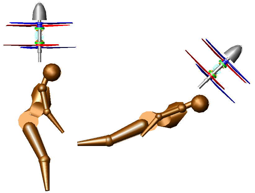
Hovering, braking, backwards motion, forwards acceleration, high speed cruising
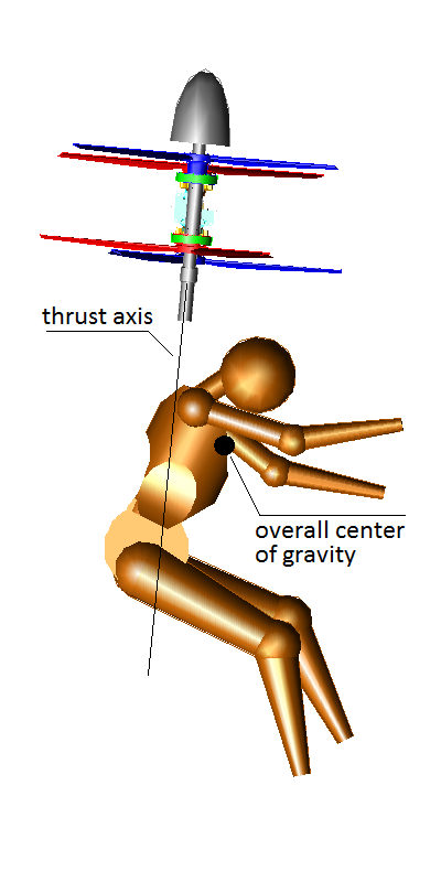
Hovering, vertiacal take-off and vertical landing:
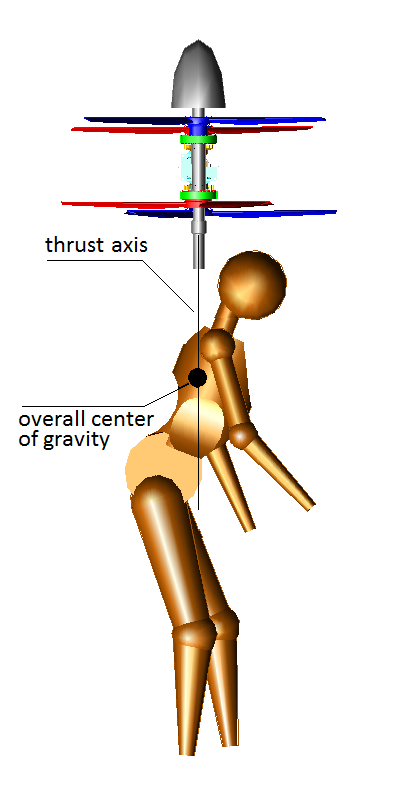
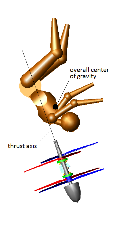
During vertical take-off, vertical landing and hovering the pilot has to bend forwards (as in the drawing) in order to keep the thrust normal to the horizon and the overall center of gravity on the thrust axis.
Transition from hovering to backwards motion:
The pilot leans his head backwards, and bends his legs / arms backwards causing the displacement of the overall center of gravity aft the thrust axis. This causes the rotation of the Portable Flyer counter-clock-wise (above drawing). The horizontal component of the thrust accelerates the Flying Device backwards. When the thrust is at the desirable direction the pilot has to restore his initial posture in order to stop the rotation and continue moving backwards parallel to himself.
The same for the braking. The Pilot moves his head / limbs in order to displace the overall center of gravity aft the thrust axis; this causes a fast rotation of the device / pilot assembly creating the necessary horizontal backwards braking force. Soon after the pilot has to re-arrange his hip / head / limbs in order to displace the overall center of gravity on the thrust axis.
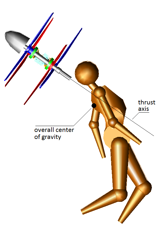
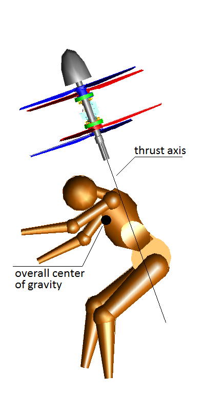
Transition from hovering to forward flight:
Being at hovering, the pilot bends his legs, hip, head and arms forwards. The overall center center of gravity is displaced fore the thrust axis creating a moment (torque) that rotates the device / pilot assembly clockwise. The more the thrust axis leans forwards, the stronger the horizontal component of the thrust force that accelerates forwards the Portable Flyer with the pilot:
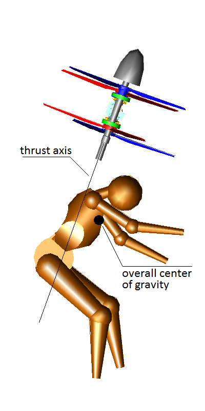
If the pilot keeps his posture, the clock-wise rotation will continue (if the Portable Flyer is at a big altitute, it will perform loops as it falls).
Cruising
When the pilot decides, he changes his body posture so that the overall center of gravity moves – initially – aft the thrust axis (in order to stop the rotation of the Portable Flyer) and then the pilot changes again his body posture in order to move the overall center of gravity on the thrust axis:
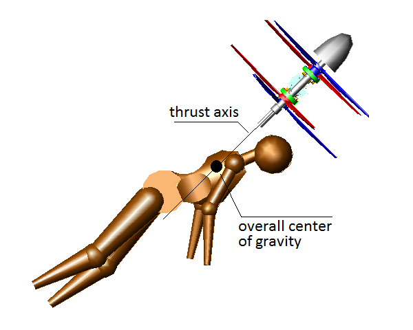
Now the Portable Flyer cruises at a velocity, with the pilot making “micro-alignments” in order to keep constant the direction of the thrust axis, with the overall center of gravity on the thrust axis. If he wants to cruise faster, he opens the throttle (this will also increase the altitude unless the pilot turns slightly forwards the thrust axis: this will increase the horizontal force without increasing the vertical lift).
All the above body postures are easy. Lying on a bed and turning to the side, one can replicate all the above posture.
In order to realize the previous modes of flight and the transitions mentioned, the weight displacement control is sufficient.
However the “aerodynamic control” is also available.
Combining the two methods, the control over the flight of the Portable Flyer goes to higher levels as compared to the existing JetPacks of Mayman / Zapata / Browning.
Worth to mention again:
It has nothing to do with a static equilibrium.
It is a dynamic equilibrium wherein the pilot feels and reacts to correct.
Suggestions
I read several suggestions to add “gimbal joints”, subframes, fuselage, seat, landing gearing, “flexures converging high”, fins, electronic control systems, etc, etc.
However without all these, the Portable Flyer in its simplest form is fully functional and fully controllable.
For such an application the simpler, the lighter, the cheaper, the more reliable, the more responsive, is the better.
In engineering a big challenge is to do more with less.
Quote from https://www.pattakon...GoFly/DTR_1.pdf
This is what the PORTABLE FLYER is: it is like an extension of the human body and it is providing the required power in a true neutral way. The brain, the senses and the muscles do the rest.
. . .
The body, the eyes and the senses of the pilot/rider are available; why not to use them as the fuselage, the sensors and the control system?
Isn’t this what the birds are doing?
Relative to the birds, the low power to weight ratio of the human body is the only thing that restricts us from flying / hovering.
This lack of power is what the OPRE Tilting engines and the propellers are curing at a true “neutral” and efficient way.
****
The OPRE Tilting needs not reed valves
A basic characteristic of the OPRE Tilting engine is the elimination of the reed valves and of the conventional rotary valves of the 2-strokes.
The tilting valves (that comprise part of the small ends of the connecting rods) do more than the reed valves and the rotary valves can do.
But it is not easy to get how they work.
The analysis at https://www.pattakon...ng_Gas_FLow.htm is a good start for discussion.
****
Is the body of the pilot of the Portable Flyer overstressed?
The positions / postures shown in the drawings of my last-but-one post are for fast transitions (say, for aerobatics).
For normal flights the required eccentricity of the overall center of gravity from the thrust axis is several times smaller.
That is, for the “basics” (smooth take off, hovering, smooth transition to medium speed cruise, cruise, smooth braking, smooth landing) the pilot’s body remains unstressed / relaxed (even old people will be able to fly it).
Normal flight versus making aerobatics is like walking versus fast running.
At hovering (say for surveillance) the posture is relaxing.
Even more relaxing is the position / posture at medium speed cruising (see the drawing): the pilot is literally lying on an air mattress and needs to make only “micro corrections”.
Can other engines replace the OPRE Tilting engines of the Portable Flyer?
Here are the characteristics of the Portable Flyer:
Zero vibrations, zero gyroscopic rigidity, zero reaction torque:
The symmetry of the engine, the zero phase difference between the two synchronized and counter-rotating crankshafts, the common combustion chamber (same instant pressure on the piston crowns of the two opposed pistons, same (and opposite) instant torque on the two crankshafts), and the symmetrical load (two counter-rotating symmetrical propellers) rids the saddle (and the pilot) of all kinds and orders of vibrations (zero free inertia forces, zero free inertia moments, zero free inertia torques, and zero combustion vibrations of all kinds). This is an absolute requirement when a powerful high revving engine is to be tightened to the body of a person.
The reaction torque is also permanently zero: no matter how wide the “throttle” is opened, or how abruptly the “throttle” opens or closes, there is no reaction torque (the only that happens is the increase or the decrease of the thrust force provided by the propellers).
The symmetry and the counter-rotation of the propellers and of the crankshafts maintains the gyroscopic rigidity of the PORTABLE FLYER zero. Even when only the one engine is running (for instance due to a malfunction of the other engine), the gyroscopic rigidity is zero. Zero gyroscopic rigidity means that the pilot “instantly” and “effortlessly” can vector the engine/propellers (i.e. the thrust force) towards the desirable 4 direction, which is an absolute requirement for a safe, accurate and instantaneous control of the flight.
Without zero inertia and combustion vibrations, without zero gyroscopic rigidity, and without zero reaction torque at the changes of the “throttle”, the control of the flight becomes slow, inaccurate, unsafe, uncomfortable and exhausting.
Two independent propulsion units are required, for safety, with each of them capable – alone – for emergency landings.
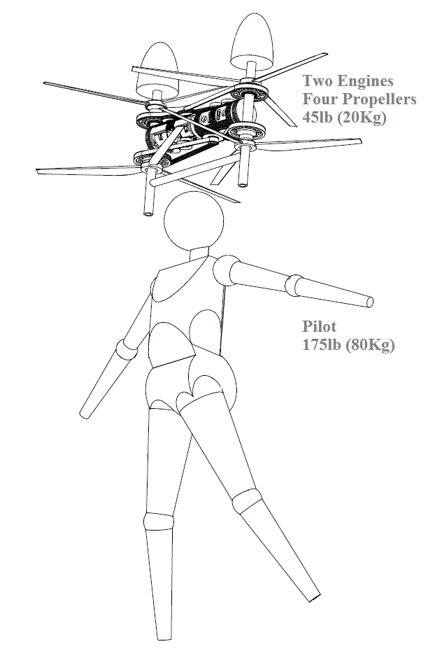
The total weight of the Portable Flyer is crucial: above 25 - 30Kg it is not wearable and the legs of the pilot are not strong enough to be used as the landing gearing.[/list]
If there are engines that comply with the previous, then yes, they could be used.
****
Weight and Flying Devices
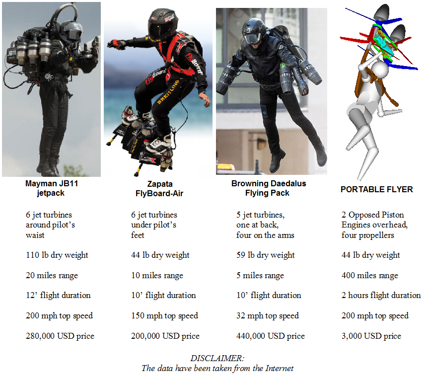
The JB11 JetPack of Mayman weighs, dry, 50Kg (110lb) :
i.e. 2.5 times more than the Portable Flyer.
For the average person, lifting 20Kg from the ground above their head is not difficult.
For the average person, lifting 50Kg from the ground to their torso height is impossible.
Worse even, for a "decent" range (say 20 miles) Mayman has to carry (to bear on his back) another 70Kg (150lb) of fuel.
For the same range the Portable Flyer needs less than 5Kg of fuel.
I.e. the overall weight of the propulsion unit (including the fuel for 20 miles) of the Portable Flyer is five times lower than that of Mayman's JB11 (20+5=25Kg versus 50+70=120Kg).
Including a 75Kg pilot, the overall take-off weight of the Portable Flyer is half than Mayman's JB11 JetPack.
Where the abovementioned 70Kg of fuel for 20 miles comes from?
According the Internet,
in order to cross the English Channel (~ 22 miles) with his FlyBoard_Air JetPack,
Zapata not only consumed 70 Kg of fuel,
but he had to land on a refueling platform, at the middle of the channel, to refuel.
And why the JetPacks have such low mileage?
The mileage has to do with the BTE (Brake Thermal Efficiency) of the engines used and with the way the thrust is generated.
The low BTE of the turbines of the JetPacks combines with a highly inefficient "propulsion method" wherein the supersonic exhaust gas takes most of the energy provided by the engine, leaving only a small percentage to the flying device.
The 1,000hp (or so) of power from their turbines, for which the JetPack makers are proud of, is indicative.
In simple words: they consume 1,000hp for something that can be done with 50hp.
To the rest requirements of a personal Flying Device (my last post) they have to be added the high BTE of the engines used and the high efficiency of the propulsion system.
For a given range, with half BTE you need to carry two times more fuel.
And with x times less efficient propulsion system (say, jets vs propellers) you have to carry x times more fuel.
While the weight of the fuel in the case of cars and motorcycles is not significant, for Flying Devices it is a crucial factor.
See the body posture of Yves Rossy and his partners:

They barely carry their Flying Devices having fuel for ten minutes of flight.
Quote from https://www.pattakon...oFly/index.html (Abstract) :
A personal flying device must be lightweight.
The more lightweight (including the fuel or the energy source) the better.
Every oz of additional (beyond pilot's) weight requires additional power and additional fuel; the added weight makes the control of the flight more difficult, the landing more risky and dangerous, the noise louder, the range shorter, the mileage smaller, the emissions worse.
A personal flying device must be as lightweight as possible; and because weight cannot be removed from pilot's body, weight can only be removed from the power unit and from the energy source (fuel or batteries).[/list]
Thanks
Manolis Pattakos
#254
manolis
-
- 940 posts
- Joined: May 03
Member
Posted 23 September 2020 - 05:51
Hello all.
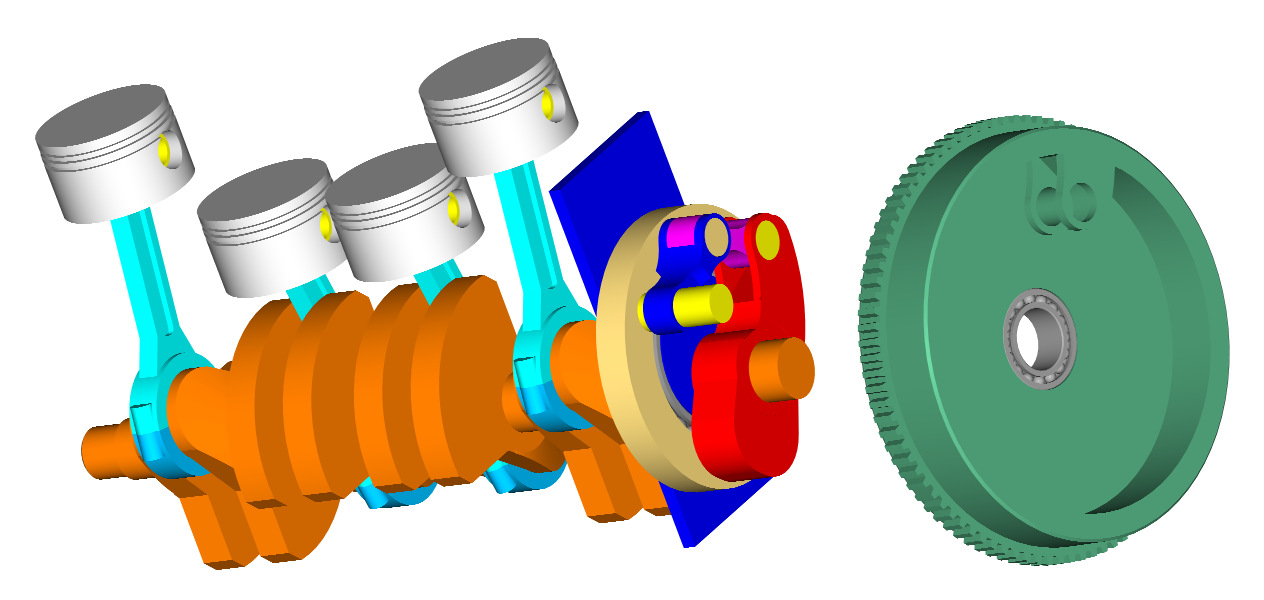
OPRRE Tilting Casting
The casing, the pistons, the connecting rods and the cylinder-end-covers are made of Aluminum A356 using “lost pattern” unbonded-sand casting.
Running at such revs is a good test.
The casting of the OPRE Tilting is a modification of the “lost foam” unbounded-sand casting method GM uses to make millions of engine blocks and other components (more at https://ferrosos.fil...hevy-blazer.pdf ) .
The pattern is not a polystyrene foam pattern, but a plastic (PLA), “empty”, 3D-printed thin shell.
The pattern is coated (actually painted) with a thin (~0.5mm) layer of plaster.
After drying for a few hours, the space around the pattern is filled with unbonded sand and the melted metal is poured:
Soon after, the part is pulled out of the sand and is drawn in water to cool down.
As in GM, the unbounded sand is reused after sieving.
HEAT TREATMENT
Later, as in GM method, the part undergoes a solution-heat-treatment (6-8 hours at 540 degrees Celsius), quench (abrupt / sudden cooling in hot water), and finally artificial aging.
SOME ADVANTAGES
Advantage of the above casting method is that it needs minimum equipment.
Strong advantage is that the modificasions are quite easy, fast and costless:
When a modification is required (say to add a branch to the casing), the CAD drawing is properly "corrected" and a different STL file is sent to the 3-D printer.
A few hours later, the new plastic pattern is ready for casting as above.
Thanks
Manolis Pattakos
Edited by manolis, 23 September 2020 - 05:59.
#255
manolis
-
- 940 posts
- Joined: May 03
Member
Posted 04 October 2020 - 08:04
Hello all.
Suppose the Portable Flyer flies nose-down (or head-down).
Can the pilot return to hovering, or to horizontal flight, and how?
Let’s simplify the problem.
Think of an astronaut wearing two small rockets rigidly secured on the left and right sides of torso / back.
Suppose that when the astronaut is at straight posture the thrust from the two rockets is parallel to astronaut’s spine.
Suppose the astronaut is 500m above the ground of the moon and is falling head-down, with the rockets pushing straight downwards. Astronaut’s body is at straight posture. The thrust passes from the center of gravity.
If astronaut’s body stays at the straight posture, the accelerating fall will continue till hitting the ground.
But the astronaut can easily change from “straight” head-down to fetal posture:

displacing the centrer of gravity away from the thrust (to the right in the photo).
Now the thrust force F is eccentric from the centrer of gravity.
According physics, the thrust force F is equivalent to an equal and parallel force F’ passing from the center of gravity, plus a torque T equal to the thrust force F times its eccentricity X from the center of gravity.
Equivalent means that the result is absolutely the same either you keep the F force, or you replace it by the force F’ and the torque T.
While the force F’ continues to accelerate the astronaut towards the ground, the torque T turns the astronaut (together with the rockets secured on astronaut’s body) about the center of gravity (COUNTER-clockwise in the photo).
I.e. the torque T turns the thrust direction.
When the astronaut has turned for 180 degrees:

the thrust is vectoring upwards decelerating the fall and then accelerating the astronaut upwards.
The astronaut has to restore to straight posture to cancel out the torque T and prevent further turning.
Is there any objection to the previous?
If not:
In comparison to the astronaut’s flight (empty space, no air), the correction from inverted flight:
to upwards flight:
of the Portable Flyer happens in the air, which means the pilot can exploit the aerodynamic forces acting on his body to turn faster.
It is a combination of the "Weight Displacement Control" and of the "Aerodynamic Control"
See how fast the wind-dancer (youtube video two posts ago) turns from “head down” to “head up” based exclusively on the aerodynamic forces applied on her body.
And talking for the wind-dancer, it is worth to note here:
the “thrust” force acting on the body of the wind-dancer (i.e. her weight) is permanently passing from her center of gravity (this is the definition of the center of gravity); if she was falling in the empty space (say in the moon), she could not start turning (if she was not turning before) and she could not stop turning (if she was initially turning).
Thanks
Manolis Pattakos
#256
manolis
-
- 940 posts
- Joined: May 03
Member
Posted 07 October 2020 - 16:06
facinating, if intake and exhaust pulses are beneficial with an even firing order engine yet its cranks rotational vibrations are detrimental to tyre wear then this mechanism will help. if im not mistaken the m1 yamaha engine has a lot of torque, taking advantage of neighbouring intake pulse sharing. if a vee four set up sharing a square airbox while using an even firing order crankshaft like on the the porsche 919, it would certaily help
Hello Pierrre.
Yesterday it was received this Search Report:
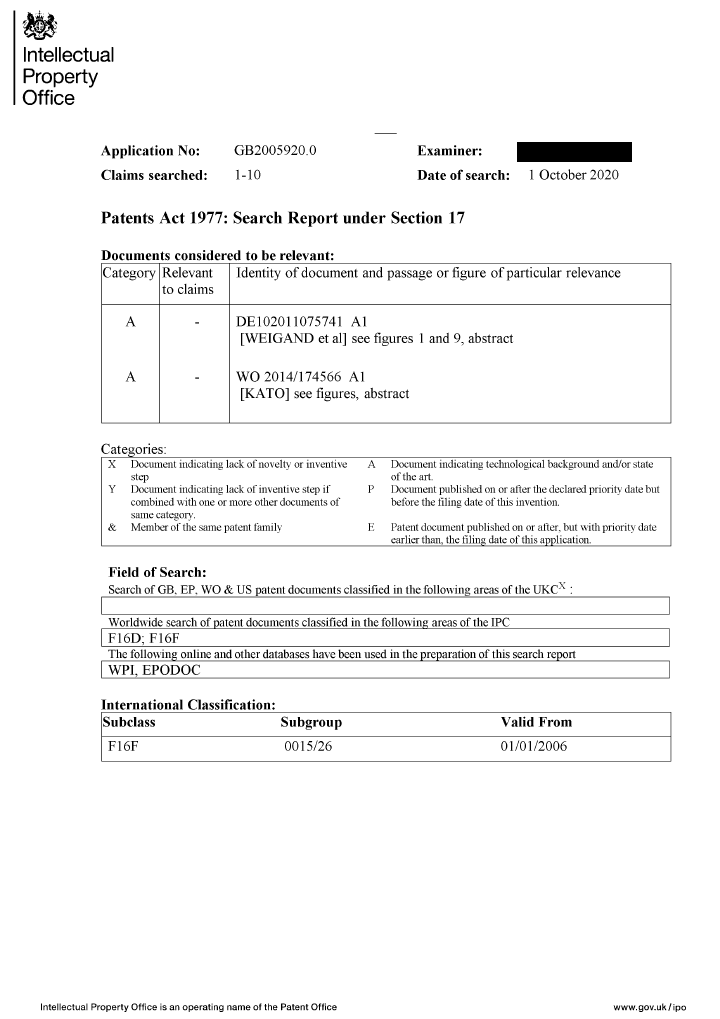
from the UK Patent Office for the PatVRA invention:
(more at https://www.pattakon...pattakonVRA.htm )
Only two “A” documents were found (“A”: Document “indicating technological background and / or state of the art”).
Here are the two documents :
and
The first is in German language, the second is in Japanese language (abstract in English).
The drawings are in the “International Language”.
The first document has the same “priority document” with the following US patent:
which is in English (granted recently: 2014).
It is interesting that both inventions mentioned in the Search Report use balance webs to take some vibrations from the rotating crankshaft.
The PatVRA needs not balance webs; it is allowing the crankshaft to perform the irregular rotation it does (variable “instant” angular velocity of the crankshaft during a rotation), allowing at the same time the primary shaft of the transmission to rev at constant angular velocity.
In a straight-four even-firing four-stroke, the PatVRA permits only the combustion pulses to pass to the gearbox (and to the drive wheel(s)), making what the Yamaha R1 cross-plane crankshaft does without sacrificing the even-firing and without adding external balance shafts.
Thanks
Manolis Pattakos
#257
gruntguru
-

- 7,706 posts
- Joined: January 09
Member
Posted 07 October 2020 - 21:34
Hi Manolis. Congratulations on a clever design.
In removing the "inertia torque" from the drivetrain, the eccentricity of your mechanism would obviously be chosen to produce constant speed at the flywheel when motored. The crankshaft will now have an increased angular speed variation (compared to the case of the same engine without your mechanism). The effect will be faster rotation around TDC and BDC (reduced piston "dwell").
Have you considered the effect on the thermodynamic cycle?
#258
manolis
-
- 940 posts
- Joined: May 03
Member
Posted 08 October 2020 - 04:46
Thanks Gruntguru.
You write:
“In removing the "inertia torque" from the drivetrain, the eccentricity of your mechanism would obviously be chosen to produce constant speed at the flywheel when motored. The crankshaft will now have an increased angular speed variation (compared to the case of the same engine without your mechanism). The effect will be faster rotation around TDC and BDC (reduced piston "dwell").
Have you considered the effect on the thermodynamic cycle?”
Let’s put some numbers to calculate the variation of the angular velocity of the crankshaft (case with no flywheel secured on the crankshaft).
Suppose you have a straight-four even-firing four-stroke having a ratio of the rotating mass to the reciprocating mass equal to 4.
Why 4?
Real figures from existing engines:
0.5Kg mass of a piston with its wrist pin and with the ~1/3 of its connecting rod
2Kg rotating mass at crankpin eccentricity (crankpin mass, plus 2/3 of the connecting rod mass, plus the 1/4 of the overall mass of the crankshaft).
If at the TDC (and at the BCD) wherein the reciprocating masses have zero speed, the angular velocity of the crankshaft is ω, and at the middle stroke (90 degrees after the TDC, wherein the center of the crankpin and the reciprocating mass move at the same speed) the angular velocity of the crankshaft is ω’, the conservation of the kinetic energy gives:
4*ω*ω = 5*ω’*ω’, i.e. ω/ω’ = SqruareRoot(5/4)=1.12
I.e. at the TDC the angular velocity of the crankshaft is 12% higher than it is 90 degrees later.
I.e. at the TDC and at the BDC the angular velocity is 6% higher than the mean angular velocity of the crankshaft, while at the middle stroke (90 degrees after the TDC) the angular velocity of the crankshaft is 6% lower than the mean angular velocity.
With a typical flywheel secured on the crankshaft these percentages reduce, say by 50% (from 6% to 3%).
So, in comparison to an existing four-cylinder car engine, the modification to PatVRA will give a 3% higher speed of the crankshaft at the TDC (and BDC) and a 3% lower speed 90 crank degrees later.
That is, if the conventional engine is running at 3,000rpm mean angular velocity, with the patVRA the combustion (which happens around the TDC) feels as if the conventional engine was revving at 3,090 rpm, while the expansion (around middle stroke) happens as if the engine was running at 2,910 rpm.
In the previous we took only the peaks.
But the combustion duration is several degrees (say from -30 to 50 degrees from the TDC), the same for the expansion.
So the above +/- 3% reasonably reduces to +/- 2%
Conclusion:
The increased rotational non-uniformity of the crankshaft affects the thermodynamics only marginally (and not necessarily in a negative way).
Thanks
Manolis Pattakos
#259
gruntguru
-
- 7,706 posts
- Joined: January 09
Member
Posted 08 October 2020 - 21:06
Thank you Manolis. It is good to put some numbers to the concept.
Advertisement
#260
gruntguru
-
- 7,706 posts
- Joined: January 09
Member
Posted 08 October 2020 - 22:00
The numbers might be different for this (generative designed) crankshaft!
https://www.autodesk...ankshaft-design
#261
manolis
-
- 940 posts
- Joined: May 03
Member
Posted 09 October 2020 - 02:58
The numbers might be different for this (generative designed) crankshaft!
Hello Gruntguru.
Even with this crankshaft design the 4:1 rotating to reciprocating mass cannot fall below 2:1.
To the crankpin mass you have to add the mass of the big end of the connecting rod and some of the mass connecting the crankpin with the neighboring crankpins or journals.
And, reasonably, the pistons / wrist pins and the flywheel will not be normal ones but lightweight.
With 2:1 rotating to reciprocating mass:
2*ω^2=3*ω'^2, i.e. ω/ω'=sqrtτ(1.5)=1.225 (instead of 1.12 in case the rotating to reciprocating mass is 4:1).
I.e. the final +/- 2% becomes +/-4%, which is still small.
For comparison, the OPRE tilting engines of the Portable Flyer have pulling rod architecture (the combustion happens around the slow Dead Center) giving an increase of the piston dwell around the Combustion Dead Center about 30%:
Worth to mention:
While the wide variation (oscillation) of the kinetic energy of the four pistons causes - at high revs - a strong (and "idling") inertia torque (that overloads the transmission, increases the noise / friction and spoils the feeling), it causes only a small (say, +/-3%) variation of the angular velotity of the crankshaft.
Thanks
Manolis Pattakos.
#262
Kelpiecross
-

- 1,730 posts
- Joined: October 10
Member
Posted 09 October 2020 - 03:15
gg - the "generative designed" crankshaft looks almost ridiculously flimsy - and it's only got three main bearings - it would be interesting to see how long it lasted in the real world.
#263
Kelpiecross
-
- 1,730 posts
- Joined: October 10
Member
Posted 09 October 2020 - 03:27
Manny - my comment on your latest engine idea - Eh?
#264
Kelpiecross
-
- 1,730 posts
- Joined: October 10
Member
Posted 11 October 2020 - 05:17
Hello all.
Suppose the Portable Flyer flies nose-down (or head-down).
Can the pilot return to hovering, or to horizontal flight, and how?
Let’s simplify the problem.
Think of an astronaut wearing two small rockets rigidly secured on the left and right sides of torso / back.
Suppose that when the astronaut is at straight posture the thrust from the two rockets is parallel to astronaut’s spine.
Suppose the astronaut is 500m above the ground of the moon and is falling head-down, with the rockets pushing straight downwards. Astronaut’s body is at straight posture. The thrust passes from the center of gravity.
If astronaut’s body stays at the straight posture, the accelerating fall will continue till hitting the ground.
But the astronaut can easily change from “straight” head-down to fetal posture:
displacing the centrer of gravity away from the thrust (to the right in the photo).
Now the thrust force F is eccentric from the centrer of gravity.
According physics, the thrust force F is equivalent to an equal and parallel force F’ passing from the center of gravity, plus a torque T equal to the thrust force F times its eccentricity X from the center of gravity.
Equivalent means that the result is absolutely the same either you keep the F force, or you replace it by the force F’ and the torque T.
While the force F’ continues to accelerate the astronaut towards the ground, the torque T turns the astronaut (together with the rockets secured on astronaut’s body) about the center of gravity (COUNTER-clockwise in the photo).
I.e. the torque T turns the thrust direction.
When the astronaut has turned for 180 degrees:
the thrust is vectoring upwards decelerating the fall and then accelerating the astronaut upwards.
The astronaut has to restore to straight posture to cancel out the torque T and prevent further turning.
Is there any objection to the previous?
If not:
In comparison to the astronaut’s flight (empty space, no air), the correction from inverted flight:
to upwards flight:
of the Portable Flyer happens in the air, which means the pilot can exploit the aerodynamic forces acting on his body to turn faster.
It is a combination of the "Weight Displacement Control" and of the "Aerodynamic Control"
See how fast the wind-dancer (youtube video two posts ago) turns from “head down” to “head up” based exclusively on the aerodynamic forces applied on her body.
And talking for the wind-dancer, it is worth to note here:
the “thrust” force acting on the body of the wind-dancer (i.e. her weight) is permanently passing from her center of gravity (this is the definition of the center of gravity); if she was falling in the empty space (say in the moon), she could not start turning (if she was not turning before) and she could not stop turning (if she was initially turning).
Thanks
Manolis Pattakos
A bit pervy maybe Manny with the "girl astronaut" pictures ? - and I didn't understand a word of it.
Edited by Kelpiecross, 11 October 2020 - 05:19.
#265
manolis
-
- 940 posts
- Joined: May 03
Member
Posted 11 October 2020 - 07:16
Hello Kelpiecross.
You write:
"A bit pervy maybe Manny with the "girl astronaut" pictures ?"
It is just a person at fetal posture.
The photo was chosen because her position is quite close to the posture shown in the Portable Flyer drawings.
You also write:
"and I didn't understand a word of it."
It explains how easily an astronaut can recover from a vertical dive.
When from straight position the astronaut changes to fetal position, a large displacement of the center of gravity happens.
The larger the offset of the center of gravity from the thrust axis, the faster the correction of the direction of the flight.
On the other hand, even if the astronaut has limited mobility (say, the astronaut can move only his/her tongue; consider that the thrust force comes from a pair of rockets secured at the sides of his/her paralyzed body), the astronaut still has full control over his/her flight: he/she flies controllably and can go at any desirable destination..
Thanks
Manolis Pattakos
#266
manolis
-
- 940 posts
- Joined: May 03
Member
Posted 15 October 2020 - 03:14
Hello all.
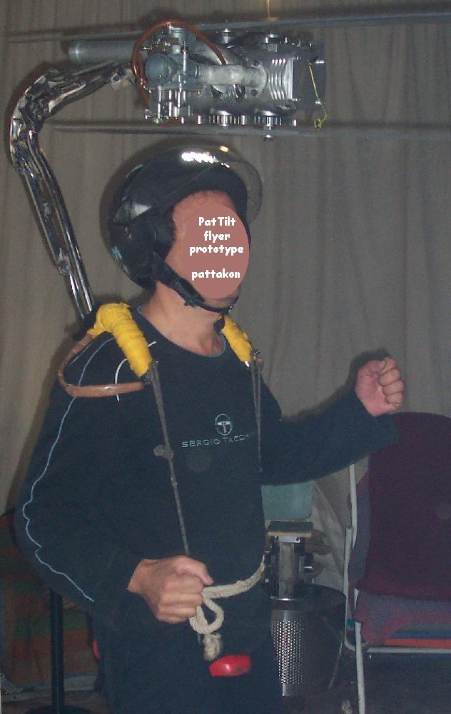
PORTABLE FLYER PROGRESS
In the following photos they are shown the first OPRE Tilting prototype engine (at the center; its casing, pistons, connecting rods and covers are made of billet aluminum “7000”) surrounded by ten “all-cast” OPRE Tilting Engines (made of A356-1 aluminum alloy (6.5-7.5% Si, 0.3-0.45% Mg); the material is from used light-alloy car-wheels):
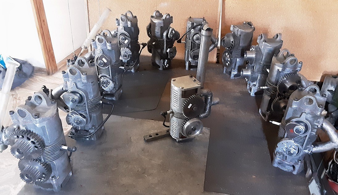
Two of the engines (4th and 5th from right, those with the short top covers), are “broom version" power plants (power output from opposite side of the two crankshafts).
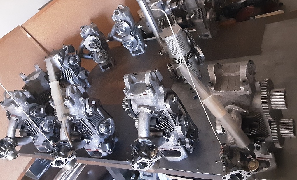
The ten "all cast" engines are for four Portable Flyers and two "Broom" Flyers.
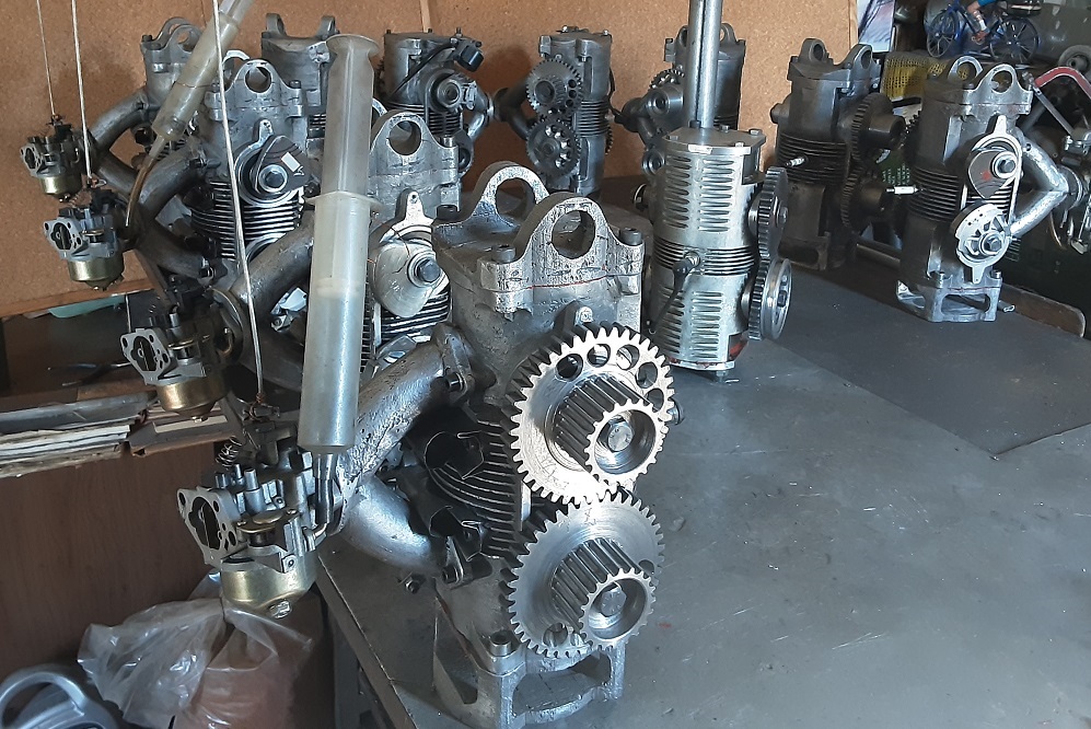
What is missing is:
the ignitions from the three engines at right (first photo),
the machining (CNC mill) of the sprockets on the hubs of the 8 synchronizing gearwheels (the rest 12 are ready),
better carburetors (or, preferably, fuel injection),
propellers with their sprockets and toothed belts,
and
the frames securing the engines to pilot's body.
Here is how the “DEVICE TECHNICAL REPORT” for the GoFly / BOEING contest begins (more at https://www.pattakon...oFly/index.html ) :
PORTABLE FLYER ARCHITECTURE AND BASIC DESIGN CHARACTERISTICS
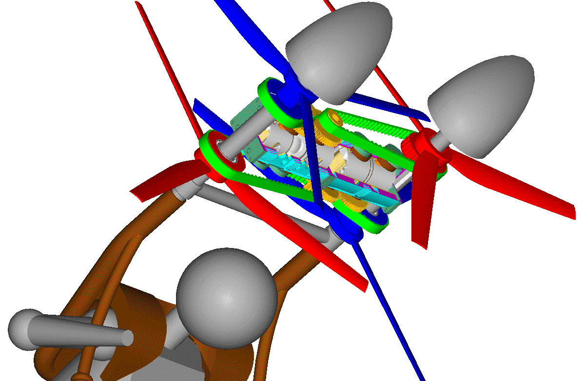
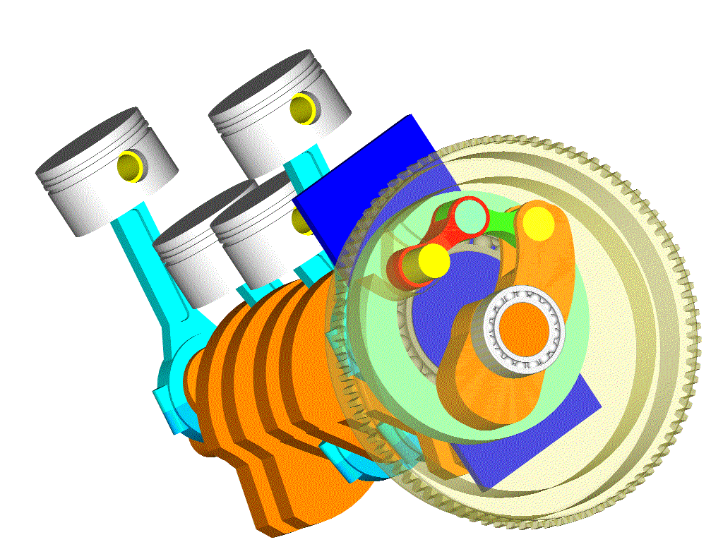
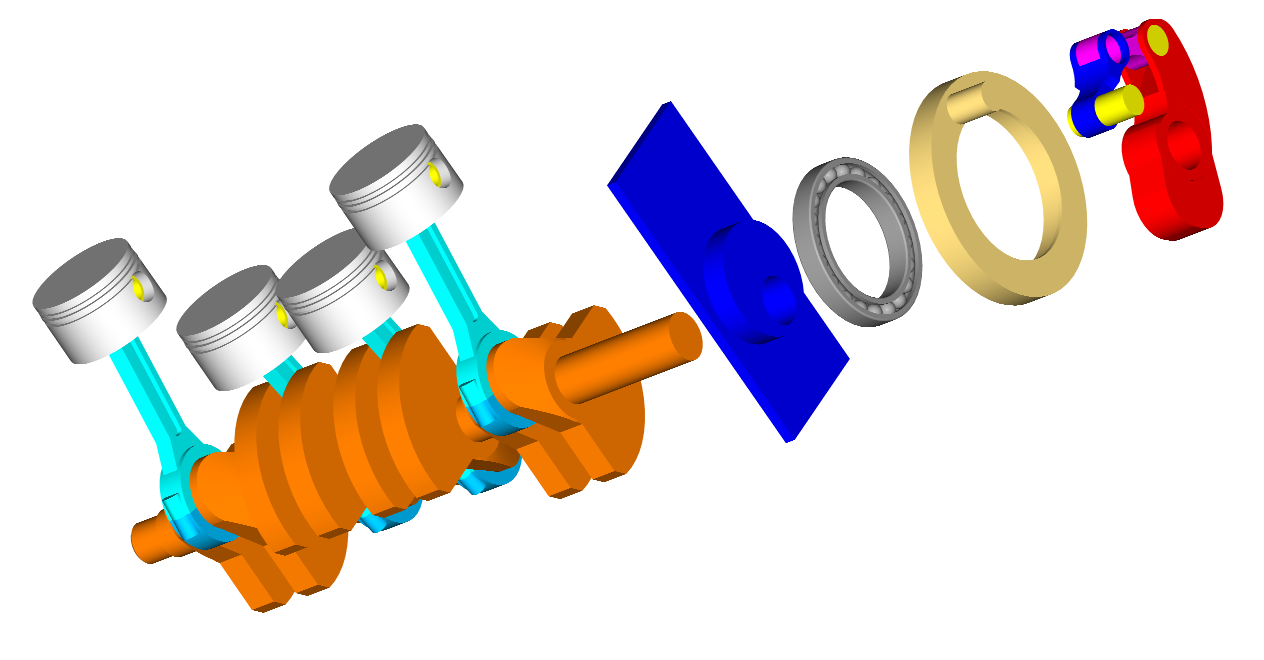
The PORTABLE FLYER comprises two OPRE Tilting Engines secured to each other to form (with their casings) the personal flying device’s “backbone”.
The one engine drives two counter-rotating propellers arranged above the backbone, the other engine drives two counter-rotating propellers arranged below the backbone.
The following presentation deliberately focuses on the engines because the PORTABLE FLYER is actually its engines . . .
Thanks
Manolis Pattakos
#267
Kelpiecross
-
- 1,730 posts
- Joined: October 10
Member
Posted 17 October 2020 - 04:33
You have certainly been very busy.
#268
manolis
-
- 940 posts
- Joined: May 03
Member
Posted 25 October 2020 - 04:08
Hello all.
Here are the specifications of the JB10 and JB11 JetPacks of Mayman:
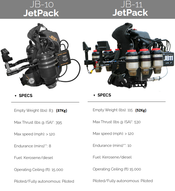
Spot on the dry weights.
Adding, say, 30 liters (24Kg) of kerosene / Diesel fuel (otherwise the flight duration will be shorter than 10 minutes), the total weight of the device at take-off becomes 59Kg (130lb) and 76Kg (167lb).
The JB11 has six turbines for safety (if one turbine fails, the functional ones allow it to fly and land safely). But this version (JB11) is too heavy. Only few people can carry such a weight on their back / legs without problem.
The JB10 is less heavy, but it cannot fly or land if the one turbine fails (the JetPack is no longer controllable: it will start spinning fast: with the center of gravity more than 0.2m away from the thrust axis (i.e. from the shaft of the functional turbine), it will make its first side loop (?) in 1.5 second, its second “side loop” will last substantially less than 1 second and so on. No case of safe landing or control.
In this photo / drawing:
Mayman (at right) wears his JB10 JetPack.
Compare the distance and location of the shafts of the two turbines with the distance and location of the rotation axes of the four propellers of the Portable Flyer (at left).
A difference between the two arrangements is the higher position of the Portable Flyer propulsion unit (higher center of gravity).
However at flight what does matter is the location of the overall thrust axis; and the thrust axis is, more or less, at the same position and passes near the center of gravity in both cases.
I.e. the big difference will be on the ground with the one unit being substantially more lightweight but arranged higher.
In both cases the “upper torso / back” of the pilot is secured to the propulsion unit. The turbines and the torso / back of the Mayman comprise a fixed body. The propulsion unit and the torso / back of Portable Flyer's pilot comprise a fixed body. Using their free body-parts the pilots instinctively control their flight in both cases.
As Mayman says, the average person needs three hours of tethered training before free low-height flights over water.
Mayman cannot use, at small / medium speeds, aerodynamic control because the air speed on his limbs / head is small (and he has to keep his limbs away from the supersonic hot exhaust gas), so he needs additional mechanisms for the yaw control. The Portable Flyer pilot has aerodynamic control from take off to landing for the yaw (and much more).
Another difference is the safety offered by the Portable Flyer: in case the one propulsion unit fails, the other with its two propellers continues to run independently, allowing both: controllable flight and safe landing.
There is no pitch control in either case.
The automatic pitch provided by the PatPitch propellers:
allows higher final speed and lower engine loads; more at https://www.pattakon...ttakonPitch.htm
Thanks
Manolis Pattakos
#269
manolis
-
- 940 posts
- Joined: May 03
Member
Posted 30 November 2020 - 06:37
Hello all.
PatVRA:
(more at: https://www.pattakon...pattakonVRA.htm )
In the following “demonstration” plot two vehicles are standing on a road:
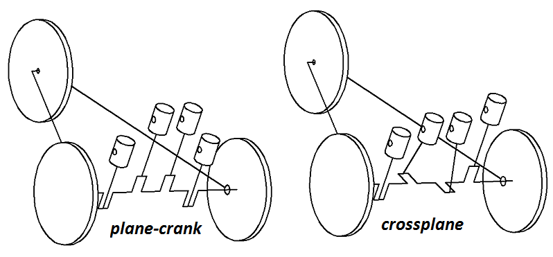
The crankshaft of the 4-cylinder engine of each vehicle (plane-crank at left, cross-plane crank at right) is the drive shaft secured on the two (rear) wheels.
The cylinders of the engines (not shown) are arranged vertically.
The cylinder heads are removed (no combustion in the cylinders).
We apply a horizontal initial push onto the two vehicles and then we leave the vehicles to move free (suppose zero friction).
The velocity of the right vehicle (crossplane crank, zero inertia torque) will be constant.
The velocity of the left vehicle will be variable:
When the four pistons are at their top and bottom dead centers (as in the plot) the velocity of the vehicle will be at its maximum (because the kinetic energy of the set of the four pistons is at its minimum).
90 degrees of wheel-rotation (or of crankshaft rotation) later, the vehicle speed will be at its minimum (because the kinetic energy of the set of the four pistons is at its maximum).
Without applying external forces to the vehicle, its total kinetic energy remains constant; if the kinetic energy of the reciprocating pistons increases, the vehicle speed decreases, and vice-versa.
With the two vehicles moving side-by-side, the left one will be ahead of the other two times per wheel rotation, and behind the other two times per wheel (or crank) rotation.
If the crankshaft of the left vehicle was connected to the wheels by two PatVRA mechanisms, then both vehicles would move at constant speed.
Things are not too different when a typical car with 4-cylinder plane-crank even-firing engine is driven on the road.
There isn’t noticeable increase – decrease of the vehicle speed, however there is a significant oscillation of energy between the vehicle and the engine causing vibrations etc.
Thanks
Manolis Pattakos
#270
Greg Locock
-

- 6,494 posts
- Joined: March 03
Member
Posted 30 November 2020 - 09:52
Aye but your crossplane crank tricycle will wiggle laterally at once per rev.
#271
manolis
-
- 940 posts
- Joined: May 03
Member
Posted 01 December 2020 - 04:02
Hello Greg Locock
The crossplane with crankpins at 0, 90, 270 and 180 degrees is Kawasaki's patent, Yamaha's product, and motoGP permanent winner for several years (better feeling of rear tire hooking)).
Without a balance shaft it will lift the one drive wheel (pushing the other drive wheel on the road) and, after 180 degrees of crank rotation, it will lift the other drive wheel. I.e. each drive wheel of the right tricycle will bounce once per rotation, with the crankshaft (looked from behind) turning clockwise and after 180 degrees turning counter-clockwise..
Things are a bit different with the plane-crank even-firing of the left tricycle: both drive wheels will bounce – together – two times per rotation.
It would be funny to see the drive wheels / drive shafts of the two vehicles as they "cruise" side by side.
Let’s suppose the two engines are powering two motorcycles.
Here is a strange plot, wherein apples are compared with oranges:
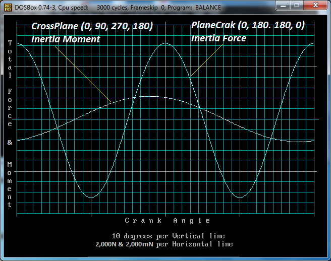
There is a ~14,000N unbalance 2nd order inertia force in the plane-crank 4-cyl while there is a ~4,000mN unbalance 1st order inertia moment in the corssplane 4-cyl engine (same pistons, same stroke, same cylinder-to-cylinder offset same r.p.m).
Let’s suppose that there are only two mounts, both at the bottom of the engine at a, say, 0.33m distance from each other, the one at the left side of the motorcycle frame, the other at the right side of the motorcycle frame.
Each of the mounts of the flat-crank engine receives a force of 14,000/2=7,000N of 2nd order (parallel forces at the same direction).
Each of the mounts of the cross-plane engine receives a force of 4,000mN/0.33m=12,000N of 1st order (parallel forces at opposite direction).
I.e. as compared to the cross-plane mounts, the mounts of the plane-crank deal with weaker forces having double frequency.
With the engines revving at the same rpm, the time the second order force of the flat-crank acts on its mount at a direction (say upwards), is half than the time the first order force of the crossplane acts on its mount before changing direction, which means the deformation of the frame at the mounts is substantially larger in the case of the crossplane because the forces are heavier and because they act at a direction for longer (suppose there are no elastic mounts).
Thanks
Manolis Pattakos


