The latest RCE has an article about a "Porsche968" Australian Time Attack car with a 4 litre four pot engine.
Here is some more on that engine- unusual to say the least
https://www.enginela...tion-meet-thor/


Member
Posted 09 January 2020 - 21:08
The latest RCE has an article about a "Porsche968" Australian Time Attack car with a 4 litre four pot engine.
Here is some more on that engine- unusual to say the least
https://www.enginela...tion-meet-thor/
Advertisement

Member
Posted 09 January 2020 - 22:35
What a beast. Interesting what can be achieved with something that goes so far outside the norms. (1 litre per cylinder !!!!!!)

Member
Posted 10 January 2020 - 04:50
Hello all.
From each aluminum connecting rod:
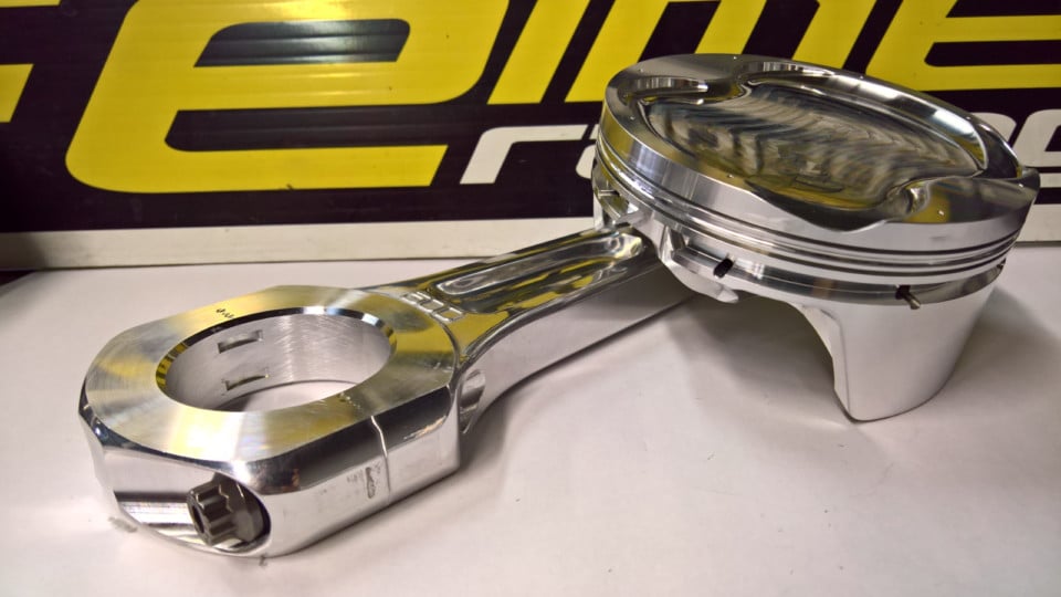
they pass 750bhp (drag-racing) or ~400bhp (circuit-racing)
The bore is 116mm, i.e. the same as Ducati's Panigale 1299.
With 1 liter capacity per cylinder, the stroke is calculated at 94mm
With the red line from 8,500 and 10,000rpm, the mean piston speed in the red line is from 27m/sec to 31m/sec.
Valves:
46mm titanium intake,
39mm exhaust,
13.2mm valve lift.
In comparison, the Ducati Panigale 1299 (same bore) has:
46.8mm titanium intake valve with 16mm valve lift,
38.2mm exhaust valve with 14.3mm valve lift,
and makes its peak power at 10,500 rpm (with the rev limiter at 11,000rpm).
It looks like their project is "no budget".
Why don't they try less conventional valve trains?
It seems that if they replace their “conventional” valve actuation mechanism by Panigale’s 1299 DESMO :
the breathing and the power output will be even better / higher.
And if instead of the single mode Panigale DESMO, the fully variable DVVA (Desmodromic VVA) were used, more interesting than the added power output it would be the operation of the enigne at partial loads / low revs / idling.
Thanks
Manolis Pattakos
Edited by manolis, 10 January 2020 - 05:38.

Member
Posted 12 January 2020 - 00:19
Their project is quite low budget, in race engine develpment terms... I doubt they could waste money on developing desmo valve actuators even if the rules allowed for such move away from the original engine. It really depends on what is said in the rule book.
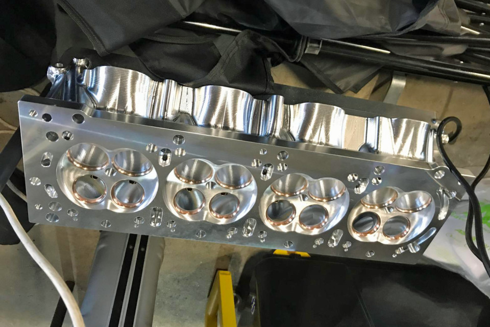
On another matter, the engine uses interesting twin turbo arrangement. Overall it is impressive for it's lightness, but not unusually powerfull, even for a 4 cyl time attack engine..
Member
Posted 12 January 2020 - 06:30
Hello Kikiturbo2
For such a project, the more power output the better.
Better breathing brings more power.
The mass-production street-legal Panigale 1299 with the same bore (116mm) and about the same intake valve diameter (46.8mm vs 46mm), has more than 20% larger valve lift (16/13.2=1.21) and operates reliably at substantially higher revs than the red-line-range of this pure race engine (11,000rpm vs 10,000rpm).
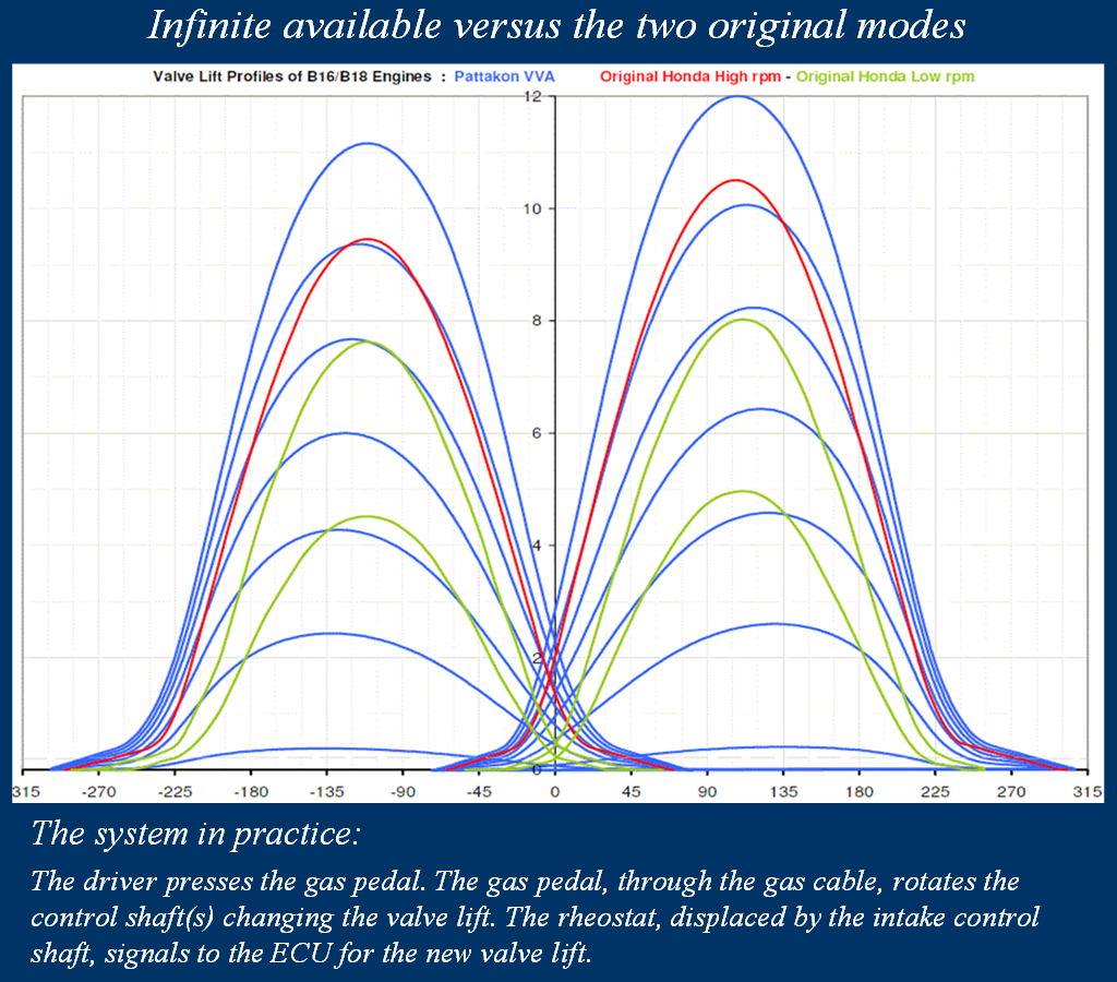
To take an idea of what a 20% larger valve lift (i.e. 20% larger valve time area) means, in the following plot the red curves are the valve lift profiles (exhaust at left, itake at right) of the original Honda V-TEC B16A2 engine (1600cc, 16v, 8,000rpm red line):
while the "only" 15% larger blue curves are the valve lift profiles of the same engine modified to VVA-roller (more at https://www.pattakon...takonRoller.htm ).
Provided their bottom end proves reliable in practice, their next version should focus on their valve train.
Thanks
Manolis Pattakos
Edited by manolis, 12 January 2020 - 06:32.

Member
Posted 14 January 2020 - 23:24
Manolis, have you considered the valvetrain is likely not the limiting factor in this car or engine? Yes, it could be more advanced, but at what cost? This thing runs and it does so quite well. One cannot live in CAD alone.
Edited by Fat Boy, 14 January 2020 - 23:30.
Member
Posted 15 January 2020 - 05:20
Hello Fat Boy.
You write:
“Yes, it could be more advanced, but at what cost? This thing runs and it does so quite well. One cannot live in CAD alone.”
The plot in my last post is not CAD.
Yet it shows the original valve lift profiles of a B16A2 1,600cc 16v VTEC sport engine of Honda (red curves for the high rpm mode, green curves for the low rpm mode) versus some of the available – on the fly – modes of the same engine modified to VVA-roller.
The tall blue curve is like the “mum” of the tall red curve (they are the intake valve lift profiles).
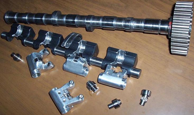
This animation is made with CAD (and more):
If you look carefully at the details, you have a lot to see.
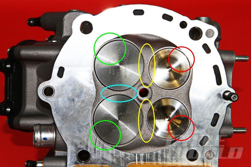
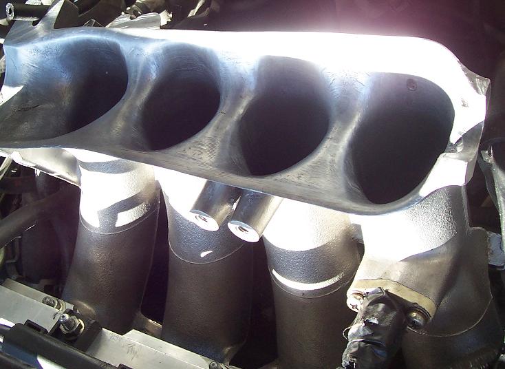
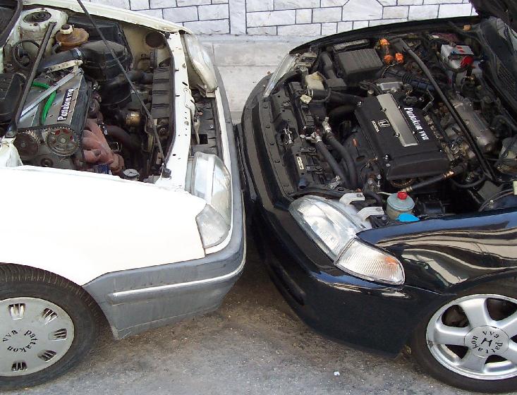
These photos are from the modified engine:
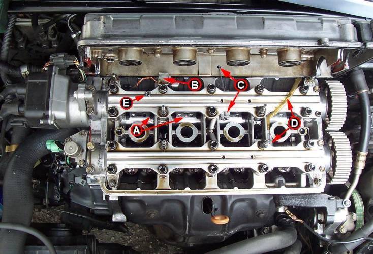
The black car is the car having the modified to VVA-roller engine (the white car engine is modified to VVA-rod):
And here is a youtube video of the modified Honda car running on the road:
The intake valve lift varies continuously from zero to 12mm.
There is not throttle valve (zero cost ITB).
The control is pure mechanical (the hydraulic control system of the original engine is removed).
The rev limiter is set to only 9,000rpm (from the 8,000rpm of the original engine) for the sake of the normal bottom end.
We made and tested them on the roads because, I gess, “One cannot live in CAD alone”.
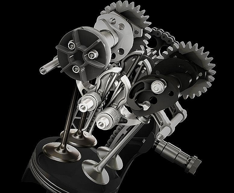
By the way, the VVA-roller of the black car, and the VVA-rod of the white car are the “father” and the “grand father” of the DVVA (desmodromic VVA), for which only a demonstration prototype has been made:
The DVVA can be considered as the combination of the other two.
For more details, you have the www.pattakon.com web site to read, you have also the presentation of the pattakon VVA’s at the International Engine Expo 2008 / Stuttgart Germany (https://www.pattakon...attakonVVAs.pps )
The guys with the expensive straight-four 1lit/cylinder racing engine should look seriously at the DVVA. They have nothing to lose. Unless the desmodromic valve trains are not allowed by the rules. Their current valve spring cost may cover the DVVA (the most expensive in the Honda VVA-roller modification was the replacement of the original valve springs by TODA racing ones).
Thanks
Manolis Pattakos
Member
Posted 16 January 2020 - 17:35
Holy 5h1t, Manolis, you actually built it? I'm damn impressed. I've seen your animations for years and figured that was about as far as it's ever gotten. No dyno curves or anything like that, but it seems as if the engine and car actually go, so chapeau for that. Ya, I pissed you off with my comment, you're gonna have to come to grips with that on your own.
As far as a desmodromic valvetrain goes, I still think it has nothing to do with the low-hanging fruit on a 4-Liter 4 cylinder. It's a turbo. If they can get the bottom end to live, they're going to throw more boost at it. Sure, at some point that also reaches diminishing returns, but I'm betting that hooking up 1500 HP (their present claim) is more than a bit tricky. My guess is they'll find speed in getting the traction control sorted before searching for more power and RPM.
Member
Posted 18 January 2020 - 05:44
Hello Fat Boy.
Thanks.
You write:
“No dyno curves or anything like that, but it seems as if the engine and car actually go”
It is far more than “more power”.
The Honda VTEC with the B16A2 engine has 100bhp/liter (160bhp from 1,600cc) making it the most powerful naturally-aspirated mass-production street-legal car engine of its time.
The red curves (high rpm mode in the plot below) is what makes this Honda engine the champion in its class.
The tall blue curves (which are like the “mums” of the red curves) of the pattakon-VVA-roller offer substantially larger valve-time-area, while the substantially lighter reciprocating “valve” mass (150gr each “complete new rocker arm” versus 260 gr of the original 2-mode rocker-arm-assembly of the Honda VTEC B16A2, Intake valve: 45 gr, Intake valve springs: 50 gr, Intake valve + (Intake valve springs)/2 + Retainer = 85 gr ) and the substantially lower friction loss into the valve-train (Honda claims a 75% friction reduction in the valve-train of their S2000 as compared to its previous – non roller cam follower – VTEC cylinder heads) allow substantially higher revs and better breathing of the modified cylinder head.
But the real improvement lies on the shorter and shorted and shorter (till zero) blue curves.
At open road the engine is like a pure racing engine.
At city roads you follow the traffic with the intake valve lift remaining below 2mm and top gear.
The feeling of a racing – at high revs - engine that behaves – at medium / low revs - as a torquey family car (or truck) engine is different than what you know.
Climbing on steep uphill roads at low speed and top gear makes more fun that speeding in the highway.
ECU remapping
The ECU, based on the present revs value X and on the present valve lift value Y (which, for the ECU, is nothing more than the original MAP signal), reads the injection duration and the spark advance at the (X, Y) cell of the modified injection and ignition tables.
The ECU modifies the injection duration and the spark advance according the signals from the rest sensors of the engine (the air temperature sensor, the exhaust oxygen sensor, the water temperature sensor etc) and triggers properly the injectors and the spark plugs.
The ECU at medium – low revs operates in closed loop mode (based on the feedback from the exhaust oxygen sensor), while at high revs it operates in open loop mode.
With 0.15mm intake valve lift the engine idles at 300 rpm.
Any valve lift from 0.15mm to 12 mm is directly available.
The engine breaths efficiently from below 1000 rpm to 9000 rpm, without steps.
When modifying an engine the difficulty is not in making more power; the difficulty is in making more power and in improving at the same time the engine at the medium / low revs and loads, and thereby improving the mileage, the feeling and the emissions.
Thanks
Manolis Pattakos
Member
Posted 18 January 2020 - 09:07
Manolis, I can imagine the engine doing everything exactly as you describe it. Others would need to see dyno charts before and after the conversion. (I would enjoy looking at them too.)
Your control system sounds a bit primitive. Giving the driver the ability to switch to a full-race cam profile at 1000 rpm (by applying WOT) is not going to produce the best results. What is really needed (as you no doubt appreciate) is for the control shaft to be actuated by a signal from the ECU so that control shaft position can be mapped to throttle position and engine speed.

Member
Posted 19 January 2020 - 04:16
I don't think even the best of VVA systems would find much use or advantage in any all-out racing class (like F1). Nor do I think (to a lesser extent) they are needed in "ordinary" cars or trucks. Their real niche is in vehicles that really do need the best of both worlds - like flasher "sporty" cars etc. - still plenty of market there though.
Member
Posted 19 January 2020 - 04:50
Hello Gruntguru.
No conventional dyno graph.
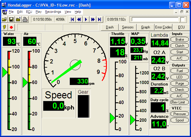
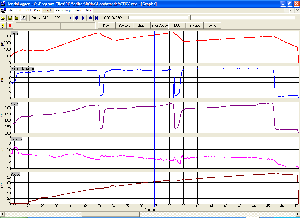
Close to a dyno graph is a plot like the following one based on the data collected on the road (with a Hondata DataLogger) :
The blue curve is the lambda value times the injection duration value, i.e. it is the quantity, per cycle, of air that is handled by the engine. At a first approach the blue curve gives the form (the shape) of the torque curve.
The red curve is the value of the blue curve times the revs (horizontal axis). Roughly speaking, the red curve gives the form (the shape) of the power curve.
The cyan curve is the MAP sensor. It gives an idea of how much the gas pedal was pressed (i.e. of the valve lift) at the specific revs.
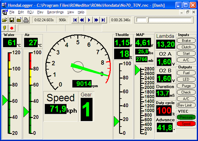
Here is another graph made with the data recorded with the same DataLogger:
In both cases the car accelerates along the same steep uphill road (highway) with the driver and a passenger.
The first plot shows the potential of the modified to pattakon-VVA-roller cylinder head at revs higher than 9,000 rpm where the rev limiter is set.
The breathing (defined, say, as the quantity of air passing through the engine per crank rotation) remains constant well above the 6,500 rpm and the 7,600rpm where the original engine makes its peak torque (150Nm) and its peak power (160ps).
At 9,000rpm the original bottom end (pistons, connecting rods) is near to fall apart.
With lighter / better pistons and connecting rods, the red and blue “curves” seem capable for continuing linearly well above 10,000rpm.
For the “indirect driving” (or drive-by-wire) of the control shaft in order to prevent over-opening of the valves when it is not necessary:
When it happens (control shaft rotated more than the optimum), it is not catastrophic: the driver just experiences the lack of torque a conventionally “tuned” engine will have at medium / low revs.
When you get familiar with it, it is similar to selecting the wrong ratio in a mechanical gear-box:
If at a low-medium speed (say at 30mph / 50Km/h) you select fifth gear (instead of second) then you know you will accelerate slowly.
Similarly, if at some low revs of the engine (say 2,000rpm) you press completely the gas pedal, the engine still pulls but not as it could with the gas pedal pressed halfway.
For the ordinary driver, instead of “drive by wire” (that puts a delay between gas pedal and the engine) it is preferable to have a displaceable “stop” (that shifts with engine revs) to prevent the control shaft from over-rotating: when the engine runs at, say, 2,000rpm the stop allows the control shaft to rotate from zero to, say, 20 degrees, limiting the maximum valve lift at, say, 4mm; as the revs increase, the stop shifts “higher”, allowing further rotation of the control shaft and larger valve lifts.
This way the simplicity is at its best as well as the direct / instant control over the engine.
Thanks
Manolis Pattakos
Member
Posted 19 January 2020 - 21:57
I disagree with your last paragraph. While this might be OK for an "enthusiast's" hobby toy, it would be ridiculous to produce a system with electronic management of most engine functions (fuel, timing etc) but with a camshaft lift control that needs to be continuously optimised by the driver (or even a mechanically mapped system as you suggest).
Remember you started with an engine fitted with electro-hydraulic control of cam switching and valve timing and removed those mechanisms.
Member
Posted 20 January 2020 - 04:42
I think the control system of the this gadget (what is its official name?) is immaterial - it can be worked out later - depending on the intended use of the device.
It would be interesting to know the history of this Patt. thing. Surely some manufacturer would have been interested in making use of the idea? What happened? If you can't "sell" something like this - what can you "sell"?
Does it have a patent number etc.?
Member
Posted 20 January 2020 - 12:57
Hello Gruntguru.
You write:
“it would be ridiculous to produce a system with electronic management of most engine functions (fuel, timing etc) but with a camshaft lift control that needs to be continuously optimised by the driver (or even a mechanically mapped system as you suggest).”
The driver optimises nothing.
When he needs more power (or torque) he presses deeper the gas pedal, and when he needs less power (or torque) he releases (completely or partly) the gas pedal (as in any other car).
The difference is that instead of increasing / decreasing the throttle valve opening through which the engine breaths, in a throttles system the gas cable increases or decreases the intake valve lift, i.e. the openings through which the engine breaths.
Alternatively, the full-version of the VVA-roller (Honda Civic, black cylinder head cover: it varies the lift of all valves, intake and exhaust):
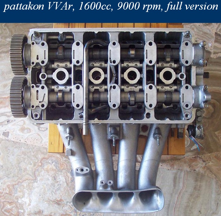
can control the load by its exhaust valves, as well; in such a case the HCCI combustion is easier to achieve and to control (trapping the necessary active radicals, say as an internal EGR). Say, like what Mazda with their SkyActivX try to achieve.
The displaceable “stop” (of my last post) prevents the control shaft from lifts above the “best maximum” for the specific revs.
The injection / ignition adjusts to the existing revs / load (with the load defined by the valve lift; while in a conventional engine the load is typically defined by the signal from the MAP sensor, in a throttles system the load can be defined either by the sub-pressure inside the cylinder (which is not easy) or by the intake valve lift).
The variable valve timing system (VVT), if any, adjusts according the revs / load, too.
An electromotor (like the 1kW Siemens electromotor used in some BMW valvetronic engines) is always an option (drive-by-wire); but the challenge is to make a system as simple as possible without loosing functionality, and as directly responding as possible (the response time of some BMW valvetronic versions is 0.3 seconds, which is not at all negligible).
Thanks
Manolis Pattakos
Member
Posted 20 January 2020 - 13:08
Hello Kelpiecross.
At top-right of each web page of the www.pattakon.com web site there are the patents (Intellectual Property) of the project presented.
For instance, the DVVA (Desmodromic VVA) writes at top-right:
Intellectual Property: patent US 8,201,531
European patent EP 2,198,129
If you get in the patent offices mentioned, you can read the patents granted.
Similarly for the rest pattakon projects.
You write:
"If you can't "sell" something like this"
There are always worse things to happen than . . .
Thanks
Manolis Pattakos


© MOTORSPORT NETWORK 2024. All rights reserved. Community Forum Software by IP.Board
