Jump to content


Photo

Early IFS


  • Please log in to reply
15 replies to this topic

#1 blueprint2002

blueprint2002
  • Member

  • 161 posts
  • Joined: May 19

Posted 19 July 2020 - 00:50

You will recall that independent front suspension (IFS) started to be widely adopted from the early thirties onwards. The GP Auto Union and Mercedes Benz come to mind, also the Dubonnet system, adopted by General Motors in the USA as well as Europe. By about the mid-thirties, the trend gained momentum, and many more companies and individuals came up with their own versions, and quite a wide variety they were.

But one thing that most, if not all, systems had in common, was that each wheel was constrained to move parallel to its original position, or you might say it maintained the same camber angle, in relation to the cars structure. Which of course, meant that when the car rolled in a turn, the front wheels rolled with it, both acquiring a negative camber (outward lean) in relation to the road surface.

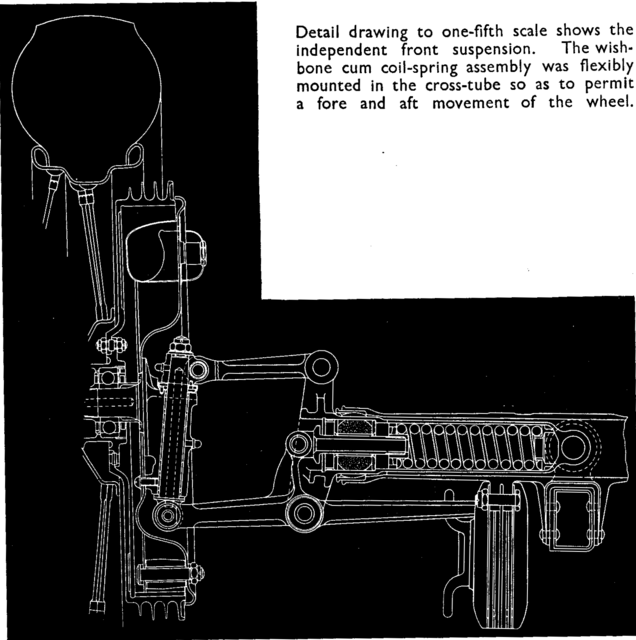
This is easy to visualise if you think of the action of any of the well-known systems of that day:

Auto Union (Porsche) twin trailing arms

Mercedes Benz parallel, equal length wishbones

Dubonnet single trailing arm

Morgan & Lancia sliding pillar

The effect of this behaviour on cornering power took a while to sink in, but when it did, perhaps around the late forties/early fifties, unequal length wishbones started to appear, gradually achieving definitive form with non-parallel static settings. From then on, it was a matter of refining the geometry to take account of circumstances, not least tyre development. (For some reason, French designers were particularly drawn to the early concept, as seen on the SEFAC, the CTA-Arsenal and the Gordini T32 Straight-8, though there were others too, such as Alta)

I have never been able to discover the reason(s) that so many designers, including the best, strove to achieve parallel movement in those early days, sometimes with quite elaborate mechanisms, many of which imposed very heavy concentrated loads where they met the chassis, almost certainly causing flexure, as well as rapid wear of the pivot/rubbing surfaces. Some descriptions point out that constant track (and sometimes constant wheelbase) was ensured by the system under review; the significance of this escapes me. Has anyone come across any literature that might provide an insight, or have any personal views on this subject?


Advertisement

#2 Ray Bell

Ray Bell
  • Member

  • 81,030 posts
  • Joined: December 99

Posted 19 July 2020 - 01:30

The same point is true of the de Dion rear suspension...


However, it's not entirely true that suspensions retained their camber relative to the body in all cases. Many wishbone suspensions in production cars, right through from the thirties to much more modern times, actually gave more positive camber to the wheels.


#3 Allan Lupton

Allan Lupton
  • Member

  • 4,060 posts
  • Joined: March 06

Posted 19 July 2020 - 08:36

I think the original point of suspension, independent or other, was to absorb road bumps so the designers concentrated on that aspect. Arranging for a simple rise-and-fall avoided the possibility of gyroscopic effects and the simpler the system the less unsprung mass there was.

Unequal wishbones, as stated above, can give camber change usually arranged so that in cornering the loaded (outside) wheel stays perpendicular to the road surface. That's the short-top-long-bottom we are all familiar with, but for some reason the Macpherson strut, which can be seen as a wishbone system having an infinitely long top link, worked well. Several systems for IFS (and IRS) worked better than one would expect in some installations but not in others - e.g. even swing axles seemed to be satisfactory if there was negative camber in the starting geometry.

Not sure what Ray means anent de Dion - like a live axle, the wheels have a fixed (usually zero) camber no matter what the car does.


#4 Charlieman

Charlieman
  • Member

  • 2,559 posts
  • Joined: October 09

Posted 19 July 2020 - 10:27

There were early designs using upper and lower quarter elliptic springs cantilever mounted transversely, hopefully with radius rods to accommodate longitudinal loads. Plus a similar design using semi elliptic springs in sliding blocks. Quite scary when one considers the effects of variable arm lengths, but less so if the springs were stiff relative to chassis rigidity.


Can anyone explain the various Alta IFS designs, please?


For information about the 1930s and later designs, I think you need to seek out academic papers. USA manufacturers were early adopters of IFS for mass production cars pre-WWII. When searching for information about the Dubonnet system I found some illustrations taken from American papers.


#5 Catalina Park

Catalina Park
  • Member

  • 6,821 posts
  • Joined: July 01

Posted 19 July 2020 - 10:30

Camber change probably wasn't really that much of a priority with 4" wide wheels.
But front axle shimmy would have been.


Edited by Catalina Park, 19 July 2020 - 10:30.


#6 Ray Bell

Ray Bell
  • Member

  • 81,030 posts
  • Joined: December 99

Posted 19 July 2020 - 11:57

Originally posted by Allan Lupton
.....Not sure what Ray means anent de Dion - like a live axle, the wheels have a fixed (usually zero) camber no matter what the car does.


Got to agree with you here, Ray was being a little silly saying that...

It's only the Rover 2000/3500 de Dion rear which has gone to some lengths to keep the wheels in their original position relative to the chassis.

As for the traditional short top wishbone and long lower one, they should give the desired camber change, but the top one needs to angle down at the inner end for that to happen and a lot of production cars simply don't have that angle.

McPherson's strut is an interesting case. It will also do the job of getting some nice camber change if it has some angle to begin with, but if you look at the first uses of these they were very close to vertical.

#7 Charlieman

Charlieman
  • Member

  • 2,559 posts
  • Joined: October 09

Posted 19 July 2020 - 12:08

McPherson's strut is an interesting case. It will also do the job of getting some nice camber change if it has some angle to begin with, but if you look at the first uses of these they were very close to vertical.

For early McPherson strut designs you need a lot of chassis in the wrong place. My understanding is that it works best with a long strut which also has the benefit of reducing bearing loads and extending life. 


#8 Ray Bell

Ray Bell
  • Member

  • 81,030 posts
  • Joined: December 99

Posted 19 July 2020 - 14:05

Peugeot went overboard when they took on the struts with the 404...


First, they kept them fairly vertical, though maybe not as vertical as they were in the Zephyrs, Consuls, Prefects and Anglias. The only other cars with them at that time, surely, were the Simca Vedette (a legacy of Ford France) and perhaps a Taunus or two.


Then they located the lower mount with a very secure set of control arms, rather than the shaky use of the anti-roll bar on the Fords.


Recognising that wear of the gland (effectively the bearing in which the shaft runs and takes the side loads) was an important durability factor, they designed them so the spring and shaft remained in place as the strut turned, a bearing under the spring plate allowing this. Thus wear on the shaft was taken around a fair proportion of its circumference.


The car's body was designed with a very effective-looking structure to carry the load from the top of the strut back to the main load-bearing areas.


I hope it's all right by Mike to use one of his pics to describe this:


0720-Peugeotstrutsupport.jpg


So there you have the top strut mount with the inner guard/fender taking the load on that side down to the buttresses which run back under the floor, while on the outside there's a box section which is pretty much triangular in shape that carries the load back to the sill box section and also to the A-pillar.


#9 blueprint2002

blueprint2002
  • Member

  • 161 posts
  • Joined: May 19

Posted 20 July 2020 - 01:07

Thanks for your responses.

First my apologies for saying "negative" camber when I should have said "positive", in my initial post.

My focus was almost entirely on single-seater (GP) racing cars, but I'm glad you have brought up various road car applications, as the perspective is so much wider.

I think my original question is answered by Allan L: avoiding gyroscopic moments which, at the time, were such a bogey.  

Happy, too, to be reminded of the Rover 2000 and its most unusual suspension, front as well as rear. A memorable car in so many ways.

C'man, I always thought that the Altas, immediate pre- and post-war, simply had their version of sliding-pillar IFS, but your remark makes me wonder if that's not so.


#10 plannerpower

plannerpower
  • Member

  • 333 posts
  • Joined: January 06

Posted 20 July 2020 - 04:48

I agree that gyroscopic effects would have been the main driver of the design of early IFS on GP cars; designers would have gained practical experience of its undesirable effects from the beam-axle designs.


The early IFS designs, although a leap-forward from the beam, had relatively small travel; the Mercedes W25, with short (5" equal-length per Pomeroy) arms, had a front suspension travel, from static to full bump, of only 1.8".


It also used coil springs and friction dampers; leaf springs, even if gaitered & greased, have some degree of damping but coils have none.


Friction dampers are not nearly as effective as the later hydraulic kind; it's worth noting that, for the later W125, Mercedes used unequal-length wishbones and hydraulic dampers.


Tyres of the time were large and heavy; per Pomeroy, the standard front tyre for the W25 was 5.25 x 17.  The weight was perhaps about 45 pounds (Jenks writes of 200 pounds for a set of W125 tyres) and much of this would have been in the tread area, representing a considerable rotating mass at high speed.


Small wonder that the designers might, with hindsight, be thought a little timid in their 1934 IFS; it was pioneering work.


But they learned quickly; three years later the W125 (per Pomeroy) had unequal-length front arms (10" & 11.8") with a static-to-bump travel of 3".  This, generally accepted as the first true long-travel "soft" (both relative terms) suspension in a GP car, was largely made possible by the development of hydraulic damping. 


Edited by plannerpower, 21 July 2020 - 02:27.


#11 blueprint2002

blueprint2002
  • Member

  • 161 posts
  • Joined: May 19

Posted 21 July 2020 - 01:14

I agree that gyroscopic effects would have been the main driver of the design of early IFS on GP cars; designers would have gained practical experience of its undesirable effects from the beam-axle designs.


The early IFS designs, although a leap-forward from the beam, had relatively small travel; the Mercedes W25, with short (5.5") equal-length arms, had a front suspension travel, from static to full bump, of only 1.8".


It also used coil springs and friction dampers; leaf springs, even if gaitered & greased, have some degree of damping but coils have none.


Friction dampers are not nearly as effective as the later hydraulic kind; it's worth noting that, for the later W125, Mercedes used unequal-length wishbones and hydraulic dampers.


Tyres of the time were large and heavy; per Pomeroy, the standard front tyre for the W25 was 5.25 x 17.  The weight was perhaps about 45 pounds (Jenks writes of 200 pounds for a set of W125 tyres) and much of this would have been in the tread area, representing a considerable rotating mass at high speed.


Small wonder that the designers might, with hindsight, be thought a little timid in their 1934 IFS; it was pioneering work.


But they learned quickly; three years later the W125 (per Pomeroy) had unequal-length front arms (10" & 11.8") with a static-to-bump travel of 3".  This, generally accepted as the first true long-travel "soft" (both relative terms) suspension in a GP car, was largely made possible by the development of hydraulic damping. 

Thank you, pp, for the detailed response.

I imagine the W25 tyres would have an OD around 30 inches, assuming an aspect ratio rather more than one. That by itself would give a large rotational inertia, to which the wire wheels themselves would add. Not sure if they had aluminium alloy rims at that time, but the spokes and hubs were certainly steel. 


#12 plannerpower

plannerpower
  • Member

  • 333 posts
  • Joined: January 06

Posted 21 July 2020 - 02:20

I erred in my earlier post with respect to the arm length; Pomeroy (The Grand Prix Car) says that they were " ... of equal length (5 in.) ... ", not 5.5" as I wrote.  I have amended my post.


But Jenks (The Racing Car) describes the W25 front suspension as having " ... a pair of wishbones of almost equal length ...".


The design is shown in this wonderful Cresswell drawing from The Grand Prix Car;


W25-Front-Suspension.png


Measurements indicate that the lower arm is about 12% longer (pivot - pivot) than the upper.


The brake drums were aluminium, probably with an iron liner; I don't know if the rims were also aluminium but DB did have a lot of experience with that metal at the time.


The Auto Union also used quite short arms in its trailing-arm IFS; just 3.75" long.


Pomeroy tells us that the torsion bars " ... gave an overall deflection of 350 lb per in., with a normal wheel movement above and below the neutral plane of 2.35 in.".


By modern standards, these cars had almost no suspension at all; we can only wonder at the men who drove them.


A good demonstration of the power of gyroscopic precession is to lift the front of a bicycle, spin the wheel and turn the handlebars sharply; the "kick" from the lightweight wheel is surprising.


Edited by plannerpower, 21 July 2020 - 08:10.


#13 Sterzo

Sterzo
  • Member

  • 5,604 posts
  • Joined: September 11

Posted 21 July 2020 - 12:19

The brake drums were aluminium, probably with an iron liner; I don't know if the rims were also aluminium but DB did have a lot of experience with that metal at the time.

According to George Monkhouse in Motor Racing With Mercedes Benz, "A great proportion of this [unsprung] weight is the tyre and wheel, which cannot be lightened very much, although modern racing wheels do have duralumin rims." He also says: "The brake drum itself is now made in two pieces, a ribbed light alloy shell with a hard steel liner pressed into it."


It's not entirely clear whether he's talking about the W125 specifically, or about the W25 too. (It's on page 25 of the Foulis 1948 edition).


#14 Roger Clark

Roger Clark
  • Member

  • 7,533 posts
  • Joined: February 00

Posted 22 July 2020 - 15:50

Quicksilver, the book of Cameron Earl’s 1947 paper on the German Grand Prix cars, has 3 ½ pages on Mercedes front suspension. He says:


”Previously, on thenType M25 (he always refers to cars by their engine type), the front Independent suspension had consisted of two swinging arms of almost equal length (upper arm 5” - lower arm 5 ½”). These arms were pivoted to a cross tube of 2 ⅝” outside diameter which was superimposed on the box section frame. The suspension arms were 5 7/8” apart at both the chassis and king-pin ends Was itself deeply recessed into the back late of the brake drum in order to reduce bearing pressure to a minimum”. 
 

“The coil springs had a rate of 15mm/100kg (1”/373lbs) and the wheels a travel of +/- 40mm (+/- 1.57”] to the stops “. 
 

“In practice, it was found that the type of suspension mounting employed on the M25 gave rise to seriousvaxial flutter, particularly under heavy breaking stresses.  For this reason, a modified front suspension system was fitted to all the GP machines at the end of the 1936 season, the most recent application of which is to be seen on thev1939 1 ½  litre (Type 165)”. 
 

he goes on the describe the W125:


”it differs slightly from that used on the 1 1/w litre machine inasmuch as both friction and hydraulic shock-absorbers are fitted. Again, the king-pin is deeply recessed into the brake back plate but with the distance between the wishbone pivot points increas3d to 6.7 inches.  The wishbones (which replace the simple arms of the M25 designs) are not of equal length, the upper one being 215mm (8.45”) and the lower one 269mm (10.59”), but they are so mounted that the effect closely approximates to that of wishbones of equal length, and the wheel remains practically vertical over its working arc.”


”in order to reduce unstrung weight still further, and simplify the design, the coil spring is mounted vertically as shown.  The spring rate is 25mm/100Kg (1”/224lbs), the overallmovement has been increased to +-70mm (+-2.75”) to the stops”.


#15 plannerpower

plannerpower
  • Member

  • 333 posts
  • Joined: January 06

Posted 23 July 2020 - 00:30

Wonderful information!


Last night I calculated spring rates of that order, using the spring dimensions (5.25" x 1.75") given by Pomeroy; the rate is strongly dependent on the wire diameter and that can only be "guesstimated" (at about 0.3") from Cresswell's drawing.


Like the front suspension, the chassis of the W25 seems to have been a small, but very important, step in the progression toward truly long-travel, "soft" suspension.


A stiff chassis is required for this kind of suspension and the W25 chassis, whilst well-designed and constructed, must have suffered from the flexibility inherent in the "ladder" design, particularly in the long area between the scuttle and the front suspension.


Little wonder that the W25 front-end experienced " ...  serious axial flutter" ; the situation sounds rather like the delightful description of the front suspension of the Shelby Cobra, with its massive anti-roll bar, as a " ... flexible beam axle".


Daimler-Benz were very aware of the problems of "shimmy"; they used the Packard "kick shackle" on some of their production cars in the early 1930s.


This device allowed a small fore & aft movement of a beam axle against a spring; the intent was to prevent transmission of  gyroscopically-induced force, produced by wheel deflection, through the axle to disturb the other wheel.  In a fast and heavy car, this could lead to serious consequences, particularly if a mechanical resonance was excited.


The kick shackle was only fitted to one side of an axle; fitting to both sides seems to have provided too much "give".  I guess that the best location on a road car would have been on the side closest to the roadside, where most road irregularities are found, but I've never seen a kick shackle or even a drawing of one.


D-B engineers provided this fore & aft movement on both sides of the W25 and on the later W125 & W163 which had much-improved chassis; the W163 allowed, per Pomeroy, +/- 0.25" of longitudinal kingpin movement.


EDIT;  It took quite a lot of searching but I now know that the Packard kick shackle is more properly known as the trunnion block; I found a picture;


Packard-Trunnion-Block.gif


Sets of four new springs can even be bought on ebay and elsewhere!


Contrary to my speculation, it was fitted to the rear of the left-hand front spring, ie the side nearest the road centreline for left-hand drive cars.


Edited by plannerpower, 23 July 2020 - 05:06.


#16 blueprint2002

blueprint2002
  • Member

  • 161 posts
  • Joined: May 19

Posted 23 July 2020 - 10:54

Thank you pp, St and RC for all that wonderful detailed data, along with insights into the subtleties of the M-B IFS during the 30s.

The description of the geometry of the W125 is intriguing in that unequal wishbones are arranged to replicate, to some extent, equal parallel wishbone behaviour.

I do not immediately recall where I have seen it, but I am certain that there were some cases where the upper and lower wishbones actually converged from frame to wheel. (Maybe some Maseratis of the 30s and 40s?) just the opposite of the now usual practice. This would certainly give wheel movement parallel to the initial position, at least over a limited range.