Jump to content


Photo

Honda RA273 1966 - was the throttle "drive by wire"?


  • Please log in to reply
17 replies to this topic

#1 amerikalei

amerikalei
  • Member

  • 404 posts
  • Joined: June 22

Posted 09 October 2022 - 17:26

I've recently been working on an old Tamiya 1/12 scale model of this car.  While I've seen lots of amazing builds on modeler forums, I'm happy to just build it clean from the old kit.  It's given me plenty to think about and appreciate in terms of the packaging of the car, but it does not look like there is a strong historical write up of it's features from any source I've come across.  The radiator pipes running along the underside of the chassis were a surprise, for example.


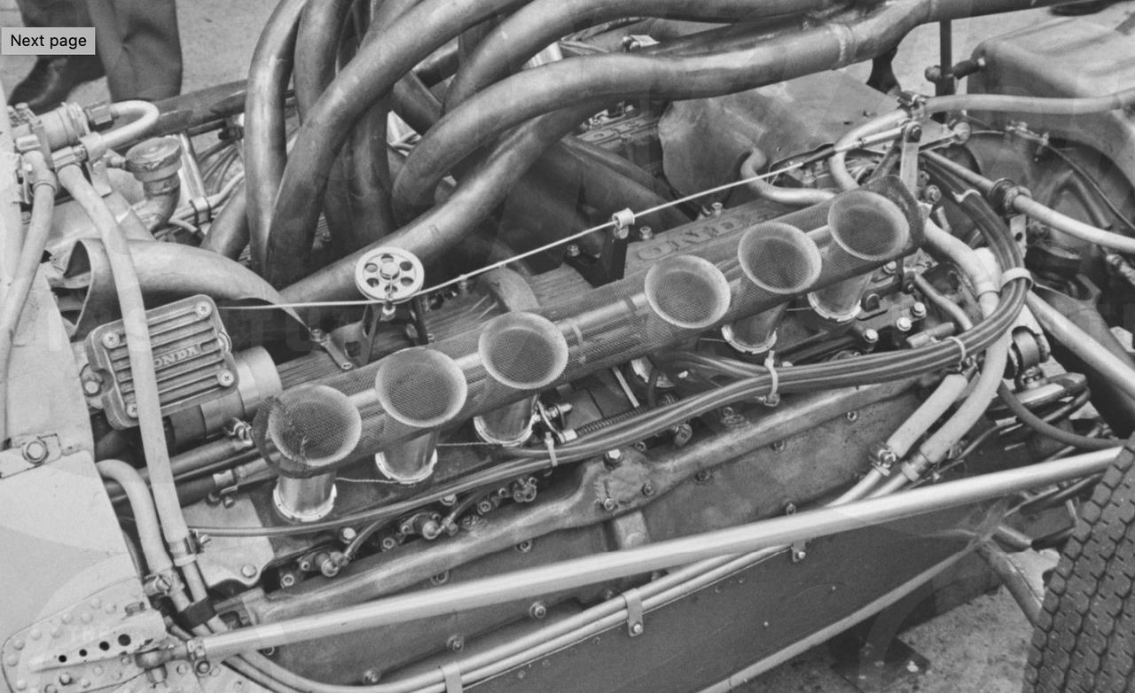
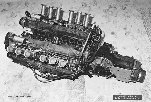
One mystery is the transistor boxes mounted behind the roll bar, which were adjacent to aluminum (presumably) air deflectors.  The throttle cable appears to emerge from the lefthand one of these and extend back to a lever mounted on a transverse shaft that spans the rear end of the engine and rotates to operate the throttle plates of each bank.  In some photos it looks like there is a wheel that deflects the path of the cable over the lefthand bank of cylinders.


So that has me wondering how the throttle cable would have been routed forward of the rear bulkhead, or were Honda playing with some sort of early transistor controlled throttle system? 


If not, I don't understand why they would not have routed the cable back along the righthand side of the chassis and simply reversed the lever end of the cable acting on the rod so that it would have been on the righthand bank.  It seems like this would have been closer to a two dimensional S-bend than the three dimensions and curves it would take to get it across the chassis.  Another possible explanation is that additional "wheels" similar to the one that was sitting over the lefthand cylinder bank were mounted elsewhere to route the cable through the chassis somehow.  Although that seems like a more complex option.


I figured this would probably be the place to ask, but if it belongs in another category, mods please feel free to relocate.


Advertisement

#2 Sterzo

Sterzo
  • Member

  • 6,427 posts
  • Joined: September 11

Posted 10 October 2022 - 09:56

If you get stuck, amerikalei, they have one in the official Honda Collection Hall at Motegi. I'd bet they'd be prepared to answer an English letter.


#3 Doug Nye

Doug Nye
  • Member

  • 11,947 posts
  • Joined: February 02

Posted 10 October 2022 - 10:19

This Revs Digital Library 1966 image would suggest not - cable, pulley and throttle-slide actuation lever evident...?


Screenshot-2022-10-10-at-11-16-07.png


DCN


#4 Myhinpaa

Myhinpaa
  • Member

  • 564 posts
  • Joined: April 11

Posted 10 October 2022 - 10:50

A photo of the engine without exhaust manifolds, which shows the crossover shaft which actuates the RH slide throttle.

Transistor box is ignition module fitted on a bracket on the tub, one for each distributor/cylinder bank. 


Honda-RA273-Engine.jpg


More details to help the model build here: https://www.britmode...honda-f1-ra273/


#5 amerikalei

amerikalei
  • Member

  • 404 posts
  • Joined: June 22

Posted 10 October 2022 - 14:16

Thanks for the responses.  That REVS photo was similar, but better to the photo I'd seen.  I just wonder how they'd do the crossover to the throttle pedal?  Which is why I brought it up, wondered if there was some sort of actuator and advanced electronics that translated inputs from the pedal.  Unlikely for the time, but the way Honda went racing as an effort to improve their engineering research seemed like it could be more to the story.


I had also seen the top view of the engine, after wondering whatever could the tool makers at Tamiya been thinking when they made the exhaust patterns.  One of the rarer views.  Anyone who's looked at the kit will know... Essentially they punted, and you build the pipes, arrange them and glue them to the rear support brackets.  Because the V has nothing, no references to the port coming from the cylinders, and the inner ends of the pipes sort of just hang there. 


The link to the britmodel site is truly amazing.  I had seen a few really intrepid builders' work.  One had fully reconstructed and added detail to the full suspension in metal.  One had adapted brake calipers from another kit to correct the "notional" moulds for the brakes.  I have great respect for the higher level of craft that some folks post.  I'm neither as skilled nor as intrepid.  But I still love old model kits as a means to learn about the relative design approaches behind these fascinating machines.


Thanks for the insights.  Seems like I may need to try to reach the museum.  If I get a response I'll be sure to post it.


#6 Bikr7549

Bikr7549
  • Member

  • 364 posts
  • Joined: May 16

Posted 11 October 2022 - 00:00

I would be very surprised if there was a throttle by wire at this point in time. Tho I agree that it sure looks like the cable protrudes from the elec box, it is possible that the throttle cable is going under the box in question, and maybe thru or around the duct work. A picture of the pedal area of the car would be interesting to see.


Despite the short length shown of the actual cable we can see in the Revs library shot above, there is a not an insignificant amount of friction in that run, plus the force needed to overcome the slide friction and the throttle return spring(s). The servo or stepper motor needed to drive this reliably (and in proximity of the exhaust heat) would have to have been pretty large to overcome this, and that box looks pretty small, tho I have to admit that I don't know what that box is since no other things can be seen attached to it. If there were 2 separate boxes to drive the right and left banks, timing across the full range of travel would have been difficult to set up and maintain. If it was throttle by wire I would think that really new aspect would have shown up in the press, or in contemporary books. None of the (few) books I have on this period mention it.


Bob


Edited by Bikr7549, 11 October 2022 - 00:04.


#7 amerikalei

amerikalei
  • Member

  • 404 posts
  • Joined: June 22

Posted 18 October 2022 - 14:22

To close this out, I had tried to email my query to Honda.  Both the US based HPD and the Honda museum in Japan were unable to provide any insight, and indicated that would be a Honda R&D question, for which they had no contact information.  Alas...


Until I have a chance to climb into an actual 273 tub head first to see how the throttle cable is routed, the answer will remain indefinite.


#8 Doug Nye

Doug Nye
  • Member

  • 11,947 posts
  • Joined: February 02

Posted 18 October 2022 - 15:15

That appears to speak volumes about the Honda museum...


DCN


#9 10kDA

10kDA
  • Member

  • 1,242 posts
  • Joined: July 09

Posted 18 October 2022 - 22:40

These two pics from Sports Car Digest show a bit more of the throttle cable. Assuming those are CDI boxes, they ran hot in that era, and the formed aluminum scoops appear to be placed to direct cold air to cylindrical objects that look like ignition coils directly beneath the CDI boxes. The pic of the car in the pits shows the cable disappearing into a relief cut in the scoop. Not saying there could not be an out-of-sight connection from the box to the cable, but it does not look like it to me.


https://cdn.sportsca...nda_ra273g.jpeg


https://cdn.sportsca...nda_ra273d.jpeg


#10 Bikr7549

Bikr7549
  • Member

  • 364 posts
  • Joined: May 16

Posted 19 October 2022 - 01:01

Didn't Dario Franchitti do a test of this car for Road & Track in recent years? I don't have my files handy but it might be worth a check on this. If not in the article he may have some contact info at Honda, if someone knows how to contact him...


#11 Bikr7549

Bikr7549
  • Member

  • 364 posts
  • Joined: May 16

Posted 19 October 2022 - 03:07

Didn't Dario Franchitti do a test of this car for Road & Track in recent years? I don't have my files handy but it might be worth a check on this. If not in the article he may have some contact info at Honda, if someone knows how to contact him...


It was the 1965 1.5 liter car, not the 3 liter. Nice article, but not that of the topic of this thread.


https://www.roadandt...5-honda-ra-272/


#12 Myhinpaa

Myhinpaa
  • Member

  • 564 posts
  • Joined: April 11

Posted 19 October 2022 - 10:24

These two pics from Sports Car Digest show a bit more of the throttle cable. Assuming those are CDI boxes, they ran hot in that era, and the formed aluminum scoops appear to be placed to direct cold air to cylindrical objects that look like ignition coils directly beneath the CDI boxes. The pic of the car in the pits shows the cable disappearing into a relief cut in the scoop. Not saying there could not be an out-of-sight connection from the box to the cable, but it does not look like it to me.


https://cdn.sportsca...nda_ra273g.jpeg


https://cdn.sportsca...nda_ra273d.jpeg


That "CDI box" is the ignition module for the LH bank, as discussed earlier in the thread. There is an identical one for the RH cylinder bank (See this photo)


As we now know, the slide throttle on the RH bank is actuated via a cross shaft from the LH lever which is actuated by the throttle pedal via the cable,

which happens to emerge from the bulkhead just under the LH ignition module. Picture which shows cross shaft and levers, here and here.


What remains to establish is the cable run and/or the mechanism, linkage, shafts etc. from the throttle pedal to where the cable emerges from the bulkhead.

The cockpit of the RA273 looks pretty closed, so it will be difficult to see with the seat and all covers/panels in place. (?)


Maybe technical drawings or a highly detailed cutaway drawing will emerge, eventually.


#13 10kDA

10kDA
  • Member

  • 1,242 posts
  • Joined: July 09

Posted 19 October 2022 - 13:28

This Revs Digital Library 1966 image would suggest not - cable, pulley and throttle-slide actuation lever evident...?


Screenshot-2022-10-10-at-11-16-07.png


DCN

Interesting adjustment to the geometry of the top radius rod.


#14 10kDA

10kDA
  • Member

  • 1,242 posts
  • Joined: July 09

Posted 19 October 2022 - 13:36


Despite the short length shown of the actual cable we can see in the Revs library shot above, there is a not an insignificant amount of friction in that run, plus the force needed to overcome the slide friction and the throttle return spring(s). The servo or stepper motor needed to drive this reliably (and in proximity of the exhaust heat) would have to have been pretty large to overcome this,

Bob

Autopilot servos installed in small general aviation aircraft in the late 60s - early 70s were designed to manage cable motion in very similar manner as required here. The servos were small, about the same size as the CDI box - sorry, ignition module - seen in the pic, and were probably comparable weight even including the electric motors. They responded quickly enough to operate a throttle. The KISS principle probably kept autopilot servos from being considered, but if anybody was to try them it probably would have been Honda. LOL


#15 Roger Clark

Roger Clark
  • Member

  • 7,574 posts
  • Joined: February 00

Posted 20 October 2022 - 12:04

Doug's photo shows the car at the 1967 German Grand Prix. It has the new exhaust system introduced at that race. The RA273 only raced once in that form as the RA300 was introduced at Monza. I don't think that we see adjustment to the geometry of the top radius arm - just holes drilled in the bracket. Honda's only attempt at weight saving in the whole car?

#16 10kDA

10kDA
  • Member

  • 1,242 posts
  • Joined: July 09

Posted 20 October 2022 - 12:46

Doug's photo shows the car at the 1967 German Grand Prix. It has the new exhaust system introduced at that race. The RA273 only raced once in that form as the RA300 was introduced at Monza. I don't think that we see adjustment to the geometry of the top radius arm - just holes drilled in the bracket. Honda's only attempt at weight saving in the whole car?

Honda designers were - maybe still are, for good reason - huge fans of double shear. The bearing is bolted in single shear to the outside of its fitting. This geometry could possibly have been employed to dial in a little more squat on acceleration if they weren't getting expected rear grip.

#17 Myhinpaa

Myhinpaa
  • Member

  • 564 posts
  • Joined: April 11

Posted 20 October 2022 - 13:57

Early versions of the RA273 seems to have two brackets on the tub for the top link, like the RA272.


'66 Watkins Glen:  https://media.gettyi...ure-id121145367


Here the top link is also fitted to the underside of the tub bracket.


#18 Roger Clark

Roger Clark
  • Member

  • 7,574 posts
  • Joined: February 00

Posted 20 October 2022 - 17:50

The top bracket was fitted after the car's first appearance at Monza.  The lower bracket remained in place but I don't think it was ever used.