Jump to content


Photo
- - - - -

Here's Everything We Learned About the Thunder Rod


  • Please log in to reply
14 replies to this topic

#1 Bob Riebe

Bob Riebe
  • Member

  • 3,003 posts
  • Joined: January 05

Posted 29 November 2022 - 22:03

Story by Lucas Bell


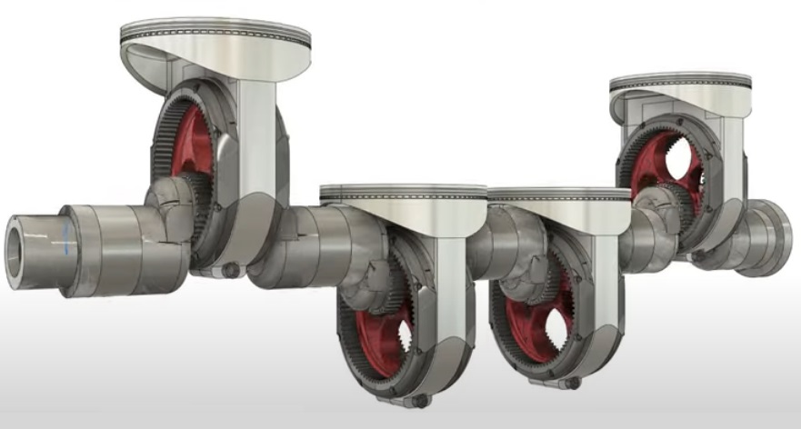
The annual SEMA Show in Las Vegas always brings fans of the automotive aftermarket loads of new hardware to check out. Transcend Energy Group made waves this week by unveiling the industry’s first two-piece connecting rod known as the Thunder Rod, which aims to improve both efficiency and performance of the internal combustion engine. R&T visited with president and chief product officer Jon Woodard on the SEMA Show floor to get a better understanding of the gains this one simple part can provide. We also spoke to industry experts to try and get their take on the Thunder Rod's viability.

This is an exciting piece of tech that has drawn a lot of eyeballs both at SEMA and in the run up to the show, offering theoretical gains through out-of-the-box thinking. It was very hard, however, to find an expert who would so much as go on the record talking about whether or not any of these claims sounded plausible in the real world. But before we dive into all that, let's talk about the basics of what's being presented.

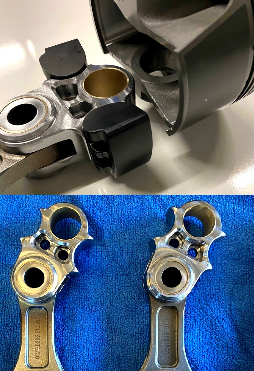
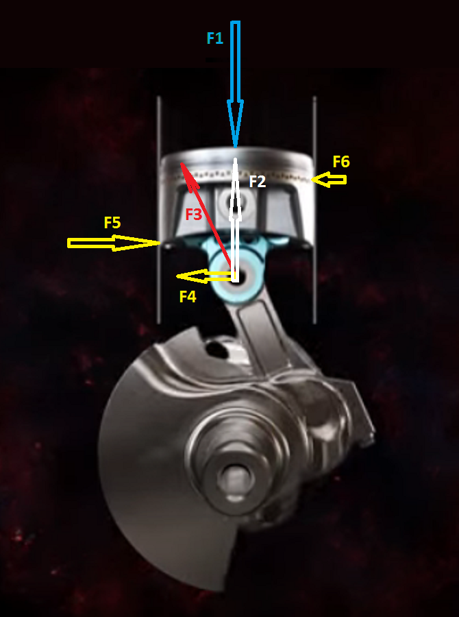
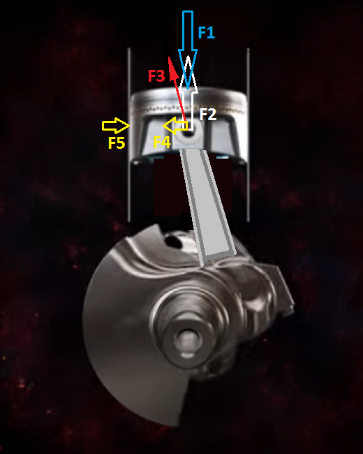
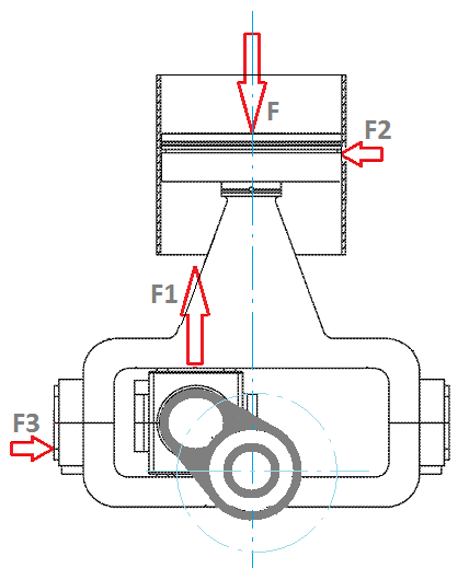
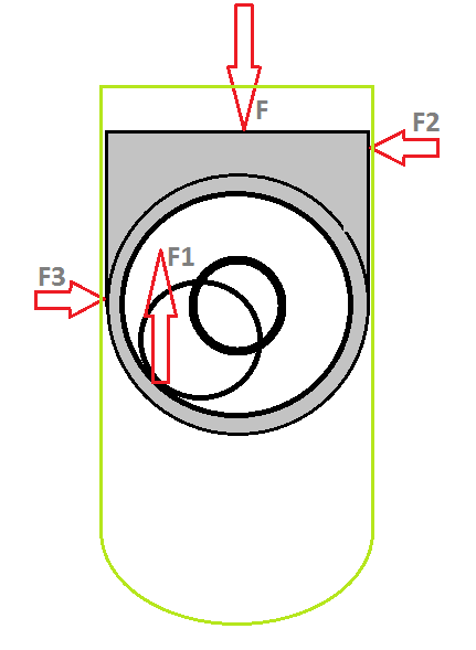
A connecting rod is not a complicated bit of engine hardware. In the basic most sense, a con-rod attaches a piston to an engine’s crankshaft, transforming reciprocating energy from the piston’s travel into the rotational energy responsible for spinning the crank. While material science and manufacturing processes have improved traditional con-rod designs over the last century or so, Transcend is the first company to roll out a two-piece unit. Instead of a traditional setup where the piston itself is a pivot point, this design moves that pivot location down onto the arm of the connecting rod. This setup creates a much more linear motion of the piston, which in turn improves the overall volumetric efficiency of the motor. Part of that comes down to the fact that the Thunder Rod uses saddles mounted inside of the piston itself to reduce piston rock and cut down on the need for thick piston skirts often found on performance pistons.


“One of the advantages that this provides is that we use the inside of the piston,” Woodward told R&T. “With the setup you don’t have to use a thick skirt. The magic is the rotation on the saddles. That allows the piston to stay neutral on the non-load side and engage only on the other side. It doesn’t try and rip itself out of there. The harder that it pushes, the more it tries to keep things flat. You can just imagine pushing something between your hand and a wall. I think in the future we’ll find that you don’t have to use skirts at all, and instead use a frictionless material like Teflon or something to make shoes that reduce that friction further.”

Development work on the Thunder Rod has been limited to 5.3-liter and 6.2-liter LS engines thus far, but there are good reasons for that. Woodward noted that the team wanted to utilize a computerized engine for data collection purposes, and the affordability of the platform overall gave it an edge over something like an overhead cam motor from Ford. It also doesn’t hurt that the aftermarket is in love with LS engines, with unrivaled part availability and research.

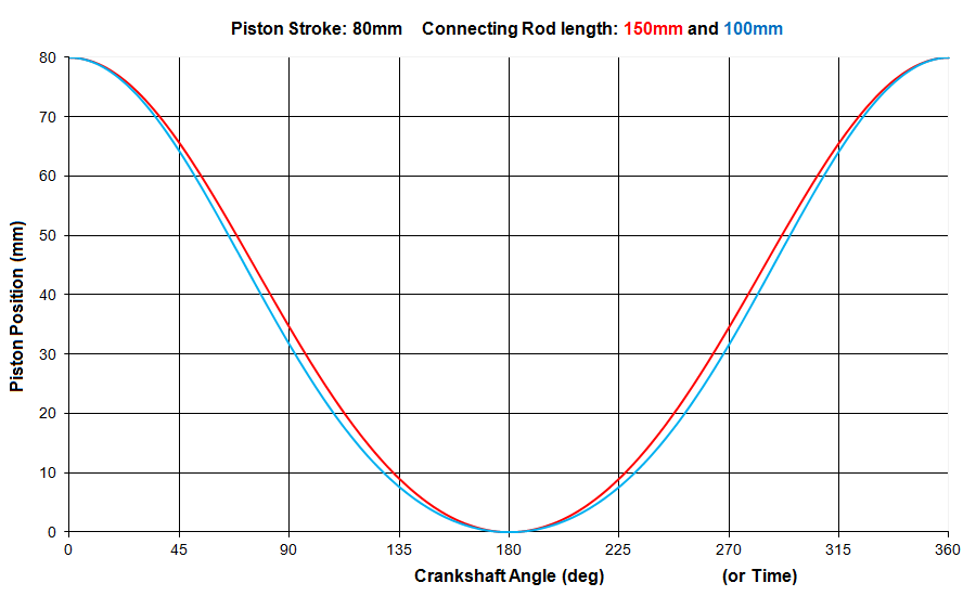
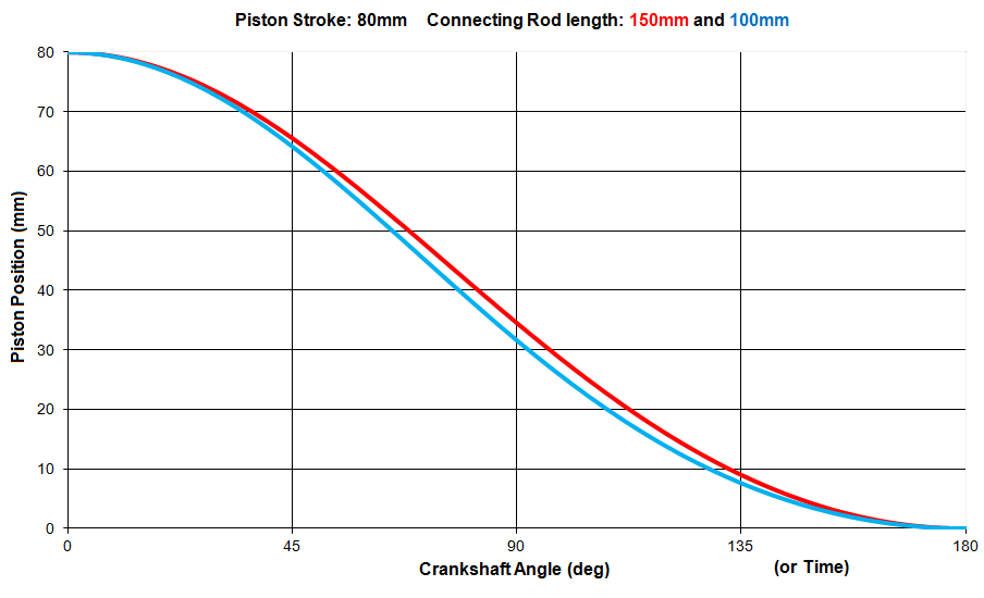
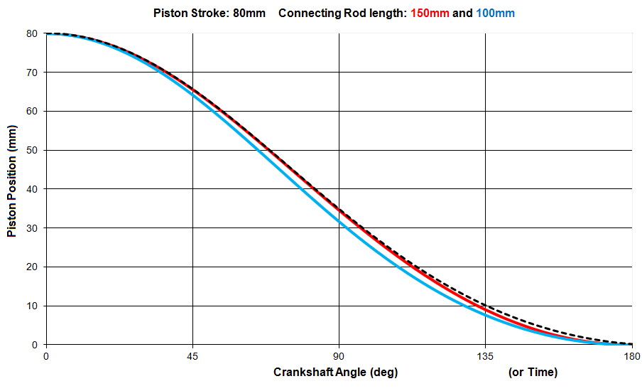
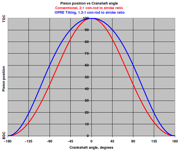
By moving that pivot point down and adding hardware inside of the piston itself, Transcend’s pistons are actually a bit heavier than a stock LS piston. The added weight doesn’t limit overall piston speed in any way, but it does change how quickly the piston moves through different parts of its stroke. The Thunder Rod increases the speed of the pistons by 30 percent off of top dead center, while providing an equal amount of dwell on the way down.

“It’s faster where it counts and it's slowed where it doesn’t really matter,” said Woodward. “When you’re drawing the air in, you want it to suck it in fast to get that intake velocity up. Once you shut the valves and start to pack the air, the slower you pack it the more air escapes through the rings. The faster you can pack that air, the more punch it has. Think about a hand pump. You can pump it slowly, but it's much more effective if you have a faster motion.”


For the time being, Transcend Energy Group is only working on testing the Thunder Rod in a stock-for-stock comparison. While they’ve already found great headroom inside the LS with just this single part, the rest of the engine isn’t really designed to function in this way. Take the pistons themselves for example, which are currently wearing a profile that doesn’t maximize the potential of the Thunder Rod. Woodward is currently working to find a more appropriate piston in the existing pool of aftermarket components. Other items like the heads and the camshaft haven’t been tuned for the system either, and could help bring even more power potential to the equation. The team is actively speaking with OEMs for their opinions on how to better improve the system collectively.

“All of the innovation that happens is the result of people taking things and thinking outside of the box,” Woodward said. “If you don’t do that and you get tunnel vision, and you think inside the norm all of the time It’s hard to create something new. People have done so much of the same. The industry is stagnated a bit with engines, which is why they’ve created better oils to keep trying to get friction out of the engines. Internal combustion engines are very inefficient, maybe 25 or 30 percent efficient. That might be closer to 60 percent in something like an F1 engine. There’s still a long way to go with the combustion engine, but we have to start thinking outside of the box.”

It is easy for a company like Transcend Energy Group to make big claims when it comes to a new product, particularly one for which they've been awarded domestic and international patents for. That said, R&T reached out to a number of engine builders and automotive experts to try and validate the performance gains being touted here. The consensus was that while the Thunder Rod is an intersting bit of engineering work, without actual data being published by the company there is little that can be said about the viability of the product.

"They claim changes in dynamic compression ratio, that would need to be measured, or I mean you could certainly calculate the piston position versus time and see how that changes," Southwest Research Institute's Kevin Hoag told R&T. "It doesn’t sound like a very big effect. If that intermediate piece is fixed in there, I struggle to see how they are eliminating piston rocking or secondary motion of the piston. I would challenge them to actually provide the calculations and demonstrate that. I think that’s generally where this design is at. There are some things that are being changed, what real effect that they have needs measurement and demonstration.

Until Transcend Energy Group is done with development of the Thunder Rod and more folks within the aftermarket get a chance to work with the new hardware, there will still be questions about the part's effectiveness. Two-piece con rods are new to gasoline-powered engines, but marine diesels and old steam engines have utilized a crosshead con rod layout for decades. Whether that speaks to the performance capabilties of the Thunder Rod will have to be seen. That said, it's exciting to see companies still invested in improving the internal combustion engine this late in its lifecycle.


Advertisement

#2 Greg Locock

Greg Locock
  • Member

  • 6,349 posts
  • Joined: March 03

Posted 30 November 2022 - 20:38

https://transcendenergygroup.com/


Pity Manolis isn't here.From the animation I can't see much difference to a standard piston's motion if it had the same conrod length and gudgeon pin to piston crown distance. There's obviously 'something' going on inside the piston.


As you can see here https://patents.goog...t/US4567866A/en and here https://patents.goog...0210180541A1/en


Edited by Greg Locock, 30 November 2022 - 20:40.


#3 TDIMeister

TDIMeister
  • Member

  • 318 posts
  • Joined: January 06

Posted 01 December 2022 - 20:15

Ah yes, this thing. It's been sucking up oxygen for weeks on the interwebs. I agree with Greg - Manolis would have a field day with this, but I can try to make a distant second fiddle.


In short, it doesn't do a thing of its chief claim, that being eliminated piston side forces. The pivot point drops lower, but a simple FBD would show that the con rods still swing back and forth (and to a greater degree at that), and the force vectors still have a transverse component that must be reacted by the cylinder.


The second claim is an increase in low-end torque in the order of 30%. Again, bunk. Being that this idea is to be dropped into existing engines, the con rods necessarily have be shorter, thus reducing the L/R ratio. People have observed that engines originally designed with lower L/R ratios tend to be low-revving lumbering beasts favouring low-end torque (but at the expense of the top-end power). These guys have taken that to the nth degree to claim that reducing the rod length as much as this concept does will increase low-end torque by ~30%. However, I have not seen any scientifically rigourous one-to-one comparisons of an otherwise identical engine build differing only in the L/R ratio showing a significant difference of torque (both peak and area under the curve). Very Smokey Yunick (R.I.P.) kind of engineering not supported by solid physics...


Edited by TDIMeister, 01 December 2022 - 20:16.


#4 TDIMeister

TDIMeister
  • Member

  • 318 posts
  • Joined: January 06

Posted 01 December 2022 - 20:19

I can tell you one thing for sure this thing would result in when incorporated in an inline 4: Much greater secondary vibrations!


Edit: piston skirt scuffing being the other sure thing.


Edited by TDIMeister, 01 December 2022 - 20:21.


#5 manolis

manolis
  • Member

  • 935 posts
  • Joined: May 03

Posted 02 December 2022 - 13:04

Hello all.


Here is a part of the US patent granted for the Thunder Rods :


Thunder_rod_US_patent.png


The inventor and the patent examiners seem to confuse the “mechanical advantage” (the “leverage”) with things like “energy saving”, “improved fuel efficiency”, “increased torque”, etc.


Here is the paragraph where the “misunderstanding” (or the catastrophe?) begins:


As is described in further detail below, the upper rod 106 of the piston assembly 100 provides a lower connection point for the lower rod 108 to connect to the piston head 104 in comparison to conventional connector rods know in the art. In particular, the upper rod 106 enables the lower rod 108 to pivot about a point that is lower relative to the piston head 104 than typical points about which conventional connector rods pivot. By having a lower point of connection (i.e., a lower pivot point), the lower rod 108 may be shorter than conventional connector rods and may reduce a lever length of the lower rod 108 . As a result, less force may be required to move the piston head 104 from the 12 o'clock position to the 6 o'clock position and/or to initiate movement of the piston head 104 from the 12 o'clock position; additionally, less force may be required to move the piston head 104 from the 6 o'clock position to the 12 o'clock position and/or to initiate movement of the piston head 104 from the 6 o'clock position. In other words, the orientation of the crankshaft 126 relative to the connection point of the lower rod 108 may provide the crankshaft 126 with better leverage (i.e., a higher amount mechanical advantage) over a translation of the piston head 104 within the cylinder 112 of the engine 102 in comparison to conventional piston assemblies.


Hello Greg Locock.

You write: “There's obviously 'something' going on inside the piston.”


Actually, and according the patent, there is nothing going on inside the piston.


Fig. 14 shows the version where the upper connecting rod is firmly secured to the piston (i.e. it is like welded to the piston). A reasonable question could be: “Then what the piston wrist pin and the upper rod are doing there? Why not to use a longer piston with wrist pin located near its bottom?”


The version with the tilting upper-rod (tilting about the piston wrist-pin) is mentioned but not explained adequately in the patent. This is another mistake of the USPTO patent examiners (who typically are engineers) because a patent must provide, to the ordinary skilled in the art, all the information required in order to built it and make it work. When the patent says “the upper rod can tilt from -15 to 15 degrees about the piston wrist pin” (paragraph 81), who prevents the upper rod from hitting the stops?


In the video:


the upper rod remains immovable relative to the piston (it is not tilting about the wrist pin). The upper rod has two cylindrical cuts wherein the dark parts (photo below) are trapped in, abutting at their other sides on the inner surface of the piston skirt:


Thunder_Rods.jpg


Their prototype is a set of eight “Thunder Rods” that replace the original con-rods of an LS V8 GM engine (the version with the upper rods secured to the piston).


The problem with the pin located well below the bottom of the piston, is that the thrust forces (and the friction, and the wear) increase:


Thunder_Rod_Forces.png


If a pressure force F1 is applied onto the piston crown, the connecting rod (the lower connecting rod) has to apply to the “lower” pin an equal and opposite force F2 along the cylinder axis. Due to the leaning of the connecting rod, and in order the connecting rod to apply a force F2 along the cylinder axis, it cannot help applying another force F4 normal to the cylinder axis, with the force F3 (which is the vector sum of the F2 and F4 forces) being necessarily along the connecting rod.


With the skirt of the piston being substantially offset relative to the force F4, the piston tilts until its lower left end to abut on the cylinder liner (where the force F5 – which is substantially larger than the F4 – is applied) and until its upper right end to abut on the cylinder liner (where the force F6 is applied). I.e. the piston and the cylinder suffer from friction and wear: instead of abutting on the cylinder liners with the one side of the piston skirt, now the piston abuts with its “corners” on the cylinder (linear contact instead of surface contact) and applies to the cylinder liner heavier forces. Also the piston rings tilt relative to the cylinder liner, worsening the sealing. Instead of the typical piston slapping, now the piston tilts and then tilts oppositely; like a wedge the piston tries to “dig” the cylinder liner.


Hello TDIMeister

As you write: “piston skirt scuffing being the other sure thing.”


In comparison, by removing the upper connecting rod and by using a longer piston (bottom right of the first image of this reply), everything is better (yet not good enough: this is why the short and very short connecting rods used in many engines several decades ago, were finally abandoned).


So, why the inventor and the “Transcend Energy Group” claim “a 30% increase of torque at middle range”?


From what is written in the patent, and from what they claim in the magazines, it seems they are confused by terms like “mechanical advantage”, “better leverage” etc, and probably they don’t yet get what the torque of an engine is, and how it is generated.


Things are simple:


The torque of an engine can be defined as the quantity of mechanical energy provided by the engine per crankshaft revolution. Instead of N*m (Newton times meters) we can measure it in J (Joules).


Power is the amount of mechanical energy provided by an engine per second, i.e. it is the torque of the engine multiplied by the revolutions of the crankshaft per second (=60*rpm).


What changes for the working gas (air or air-fuel mixture) in the cylinder when a conventional connecting rod is replaced by a Thrunder Rod?

With the Thunder-Rod the piston is faster around the TDC and slower around the BDC.


How much?


With the (lower) connecting rod being, say, 2/3 of the original connecting rod (100mm instead of 150mm for an 80mm piston stroke) the piston moves 5% faster around the TDC where the most important things happen: the combustion and the beginning of expansion.
 

Thunder_Rods_Effect_1.png


At 80mm is the TDC, at 0mm is the BDC.

The red curve is the piston position in case of a conventional engine, while the blue curve is the piston position in case the 150mm conventional con-rod is replaced by a 100mm Thunder Rod.


Thunder_Rods_Effect_2.png


At left top is the TDC, at bottom right is the BDC.


Thunder_Rods_Effect_3.png


The same plot as before, with the addition of one more curve.

The black dashed curve is the blue curve in case the crankshaft rotates 5% slower (say, at 3,800rpm instead of 4,000 rpm, with the horizontal axis being – in this case – the time). The black dashed line coincides with the red line from the TDC until middle stroke. 


So, according the geometry, when the engine with the Thunder Rods revs at 3,800rpm, the working gas sees the piston approaching the TDC and going away from the TDC as if it were in the conventional engine running at 4,000rpm (the opposite happens for the angles around the BTC). This means that the fuel burns the same way and at the same efficiency, making the Thunder Rods engine revving at 3,800rpm, and the conventional engine revving at 4,000rpm, to provide, per crankshaft rotation, the same – more or less – mechanical energy onto their pistons.


For the rest, the kinematic mechanism under the piston transforms the “linearly” provided mechanical energy by the working gas to the piston, into “rotational” mechanical energy on the crankshaft.


Due to the increased thrust loads (larger leaning of the con-rod plus forced tilting of the piston due to the distance – along the cylinder axis – of the pin from the piston skirt) the Thunder Rods engine cannot help having a higher friction loss (lower mechanical efficiency), resulting in lower torque.


According the previous, the claim for 30% more torque with the Thunder Rods in the middle range is not at all justified by the theory.


If something is confusing or unclear, please let me know to further explain.


By the way:

According the previous plots, a big change of the actual length of the connecting rod (from 150 to only 100mm) brings only a small change of the piston position per each crank angle.

If a big change of the piston position vs crankshaft angle is required, one can go from the conventional “pushing” connecting rods to the unconventional “pulling” connecting rods:


Tilting_Piston_Position.png


With the pulling connecting rods the combustion is shifted to the slow dead center (more at https://www.pattakon...attakonOPRE.htm ).


Thanks

Manolis Pattakos 


#6 TDIMeister

TDIMeister
  • Member

  • 318 posts
  • Joined: January 06

Posted 02 December 2022 - 18:42

Hi Manolis,


You have been greatly missed here. Nice to have you back contributing to excellent and detailed discussions again.


Regarding the "lever arm" affecting engine torque, this is an old, tired and totally incorrect trope, again, probably popularized by non-engineers who published books on performance engines... (who I admired in my younger, more ignorant and impressionable days of consuming car magazines and books but did not have the engineering training and experience I have now - nevertheless, I still admire them, to be clear). Because it makes a sliver of sense to intuition and may even show anecdotal results that support the argument in a limited case, it has been taken as hard fact and robust physics by a wide lay audience, which it is not.


I'm a thermodynamicist before a mechanic - the work developed by an engine is defined as the cyclic integral of P*dV, P being equal to gas force * piston area. Where the "lever arm" force acting on a crank resulting in a moment torque M = r x F (x means cross product, not scalar multiplication) might be higher at a certain crank angle or range of crank angles, they will be less elsewhere so that the integral of P*dV over the whole 720°CA of a 4-stroke cycle but particularly in the expansion phase, which has a clear thermodynamic relationship that doesn't care about the mechanical or kinematic arrangement, remains respected. I am specifically excluding temporal effects on the combustion process itself as Manolis has already covered


On another note, I would appreciate your input in this thread: https://forums.autos...adan-i4-engine/


Edited by TDIMeister, 02 December 2022 - 19:27.


#7 Magoo

Magoo
  • Member

  • 3,694 posts
  • Joined: October 10

Posted 02 December 2022 - 19:44


I'm a thermodynamicist before a mechanic - the work developed by an engine is defined as the cyclic integral of P*dV, P being equal to gas force * piston area. Where the "lever arm" force acting on a crank resulting in a moment torque M = r x F (x means cross product, not scalar multiplication) might be higher at a certain crank angle or range of crank angles, they will be less elsewhere so that the integral of P*dV over the whole 720°CA of a 4-stroke cycle but particularly in the expansion phase, which has a clear thermodynamic relationship that doesn't care about the mechanical or kinematic arrangement, remains respected. I am specifically excluding temporal effects on the combustion process itself as Manolis has already covered


Bingo. Perfectly stated. That part of the sales pitch jumped out at me as well. 


#8 TDIMeister

TDIMeister
  • Member

  • 318 posts
  • Joined: January 06

Posted 02 December 2022 - 22:14

I goofed. pressure = force divided by area, not multiplied. The onward discussion and conclusions are not impacted, however.


#9 Lee Nicolle

Lee Nicolle
  • Member

  • 11,036 posts
  • Joined: July 08

Posted 03 December 2022 - 01:15

A quick peruse of this is that they are trying to reinvent the wheel.   

2 rods are heavier and a shorter rod will reduce torque. And possibly wear the pistons far more as well.


#10 desmo

desmo
  • Tech Forum Host

  • 29,343 posts
  • Joined: January 00

Posted 04 December 2022 - 20:09

I'm a thermodynamicist before a mechanic - the work developed by an engine is defined as the cyclic integral of P*dV, P being equal to gas force * piston area.

So often, looking at an engine question from a thermodynamical standpoint rather than in terms of mechanical levers cuts right through the funny business.


#11 Magoo

Magoo
  • Member

  • 3,694 posts
  • Joined: October 10

Posted 06 December 2022 - 14:53

The Thunder Rod reminds me a little bit of one of my favorite automotive humbugs, the Powell Lever engine.  


#12 manolis

manolis
  • Member

  • 935 posts
  • Joined: May 03

Posted 07 December 2022 - 03:29

Hello all.


Things are simple:


The torque of an engine can be defined as the quantity of mechanical energy provided by the engine per crankshaft revolution. Instead of N*m (Newton times meters) we can measure it in J (Joules).


Power is the amount of mechanical energy provided by an engine per second, i.e. it is the torque of the engine multiplied by the revolutions of the crankshaft per second (=60*rpm).


A mistake: Instead of (=60*rpm), the correct is (=rpm/60).


The above quote may be confusing for some readers. 


The following drawing explains how from the torque it is calculated the energy and then the power:


torque_energy_power.png


Thanks

Manolis Pattakos


#13 manolis

manolis
  • Member

  • 935 posts
  • Joined: May 03

Posted 13 December 2022 - 05:33

Hello all.


THRUST LOAD / SLAPPING / ROCKING


As explained in the previous, with the “Thunder Rods” the piston slapping of the conventional engine changes to piston tilting (or rocking), and the thrust force of the conventional engine changes into two eccentric thrust forces.


Note: in the last half of the US patent granted for the “Thunder Rods”, the inventor seems to try to solve the piston tilting issue and the heavier thrust loads issue of his design. He proposes several ways for the support of the upper connecting rod to the piston, but none of them can work. As long as the small end of the lower connecting rod is “below” the bottom of the piston, increased thrust forces and a rocking-couple on the piston are unavoidable. This explains why the prototype has the upper rods firmly secured to their pistons.


Here is a conventional engine:


Thunder_Rod_Conventional_Forces.png


and here is the above engine with “Thunder Rods” :


Thunder_Rod_Forces.png


The F4 in the conventional is substantially weaker (edit: relative to the F in each case) than the F4 in the “Thunder Rods” engine (larger leaning of the lower connecting rod).

Due to the “weak” F4 in the conventional engine, the resulting thrust force F5 between the cylinder liner and the piston skirt is also weak (it is equal and opposite to the F4).


The heavier F4 of the “Thunder Rods” design creates an even heavier force F5 plus another force F6. Energy is consumed into friction as these forces (F5 and F6) travel up and down the cylinder. Depending on the height of the piston skirt, the Thunder Rod may have twice as much friction as the conventional.


And talking about thrust loads:


In the Alfadan I-4 engine (discussion at https://forums.autos...adan-i4-engine/ ) :


Alfadan_Thrust_Torque.png


the resulting thrust load is a rocking pair (torque):


The only who can apply a vertical reaction (reaction to the F) force to the piston is the square bearing on the crankpin: F1=-F.

But the two forces are eccentric. The rocking pair of (F, F1) tries to turn the piston clockwise.

The cylinder wall and the lower bearing can apply only horizontal forces F2 and F3. The rocking couple of (F2, F3) prevents the rotation of the piston clockwise.

The longer the eccentricity of F2 and F3, the weaker the F2 and F3, This is why is is preferable the boxer design (which, by the way, avoids the lower bearings on the crankcase).     


In the Harmonic I-4 engine ( of Graig? ) :


Harm_1.png

Harmonic_4_in_line.jpg


the resulting thrust load is also a rocking couple (torque). The F force on the piston needs a reaction. The reaction F1 is eccentric to the F. Only the walls can keep the piston from not rotating. The longer the piston, the better (i.e. the boxer has less friction).


*************


EDIT

The abovementioned "thrust" rocking couples change direction every time the piston passes from the TDC and BDC, making the piston lean the opposite direction, spoiling, among others, and the sealing.


*************


In comparison to the previous (the conventional included), in the Harmonic Reciprocating Piston Engine (more at: https://www.pattakon...PE.htm#harmonic ) , either with single-sided pistons:


HARMO2.gif


or with double-sided pistons:


Harmonic_Alfa.gif


the thrust load is negligible (******** EDIT: and permanently at the same direction*******).

It is easy to think why: the piston pin performs its linear motion either with the piston on it, or without the piston.

Think, in comparison, what happen to the connecting rod if in a conventional engine the piston is removed.


Thanks

Manolis Pattakos


Edited by manolis, 13 December 2022 - 07:29.


#14 Fat Boy

Fat Boy
  • Member

  • 2,594 posts
  • Joined: January 04

Posted 13 December 2022 - 16:52

Hello all.

.....

Think, in comparison, what happen to the connecting rod if in a conventional engine the piston is removed.


Thanks

Manolis Pattakos

Having experienced that exact scenario on a number of occasions, I can confidently state that I am against it.


#15 Canuck

Canuck
  • Member

  • 2,384 posts
  • Joined: March 05

Posted 27 December 2022 - 19:08

😀