Jump to content


Photo
- - - - -

Help - falling rate compression spring


  • Please log in to reply
13 replies to this topic

#1 kevins

kevins
  • Member

  • 146 posts
  • Joined: August 10

Posted 09 February 2023 - 11:43

Hi, this is not an automotive application, just a project I'm working on (and as is obvious I'm no mechanical engineer).


I have a small rod (5mm dia) that is being pushed over a distance of 11mm with a decreasing force and want to resist that force on the other side with a spring.


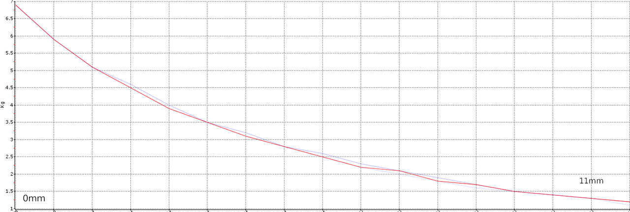
I figure I need a compression spring with a falling rate. Here is a rough force curve.


autosport.png


I found this solution, but not sure if it will work?


https://www.mwspring...ng-spring-rate/


I don't need to match my curve exactly so 2 or 3 individual rates would do.


Thanks :)


Advertisement

#2 Greg Locock

Greg Locock
  • Member

  • 6,367 posts
  • Joined: March 03

Posted 09 February 2023 - 22:12

It will work. Softening springs are hard to do without a mechanism, but if you can do it with two links and a rotational spring at the hinge between them you'll get the characteristic you've drawn.


#3 manolis

manolis
  • Member

  • 935 posts
  • Joined: May 03

Posted 10 February 2023 - 03:49

Hello Kevins.


Here is a solution of your problem:


PatEf_Anim_fast.gif


PatEf_3.png


PatEf_5.png


And its application on a V-belt CVT:


PatEf_13.png


For more: https://www.pattakon...ttakonPatEf.htm


Thanks

Manolis Pattakos


#4 Greg Locock

Greg Locock
  • Member

  • 6,367 posts
  • Joined: March 03

Posted 10 February 2023 - 09:04

That'll give a rising rate.

           o

          / \

         /   \

----->/     \<------


Is my suggestion where the o is a pivot and a torsional spring


#5 mariner

mariner
  • Member

  • 2,334 posts
  • Joined: January 07

Posted 10 February 2023 - 09:33

Ironically I think you are trying to do what generations of single seater designers in particular have tried to avoid !


Most single seaters have to have inward sloping coil spring damper unts. They weaken the effective wheel rate as the suspension compresses.


Manolis's top animation is basically looking at single seater head on. 


#6 manolis

manolis
  • Member

  • 935 posts
  • Joined: May 03

Posted 10 February 2023 - 11:05

That'll give a rising rate.

           o

          / \

         /   \

----->/     \<------


Is my suggestion where the o is a pivot and a torsional spring


Hello Greg.


Locock_spring.png

Thanks

Manolis Pattakos


#7 kevins

kevins
  • Member

  • 146 posts
  • Joined: August 10

Posted 10 February 2023 - 12:32

Greg, Manolis and Mariner, many thanks for your replies.


Unfortunately, I don't really understand them! Nor do I think I could fabricate them as I just have access to very basic tools such as a hacksaw and drill.


Looking at the solution I linked to, after giving it more thought, I don't think it will work for me. When the first (higher rate) spring is fully compressed, this means my rod has moved out say half way. But, by that point, the the force is can apply will also have decreased, so the first spring will start to open again? I'm sure I did not explain that well.


#8 manolis

manolis
  • Member

  • 935 posts
  • Joined: May 03

Posted 11 February 2023 - 04:49

Hello Kevins.


These drawings may help:


Kevins_Spring_1.gif


As the angle of the srings increases, and despite the fact that the springs are further compressed, the total "spring force" reduces.


Kevins_Spring_2.gif


The above from another view point:


Kevins_Spring_3.gif


Think the case (not shown) wherein the springs get completely vertical to the long axis of the two rods. The srpings are "completely" compressed, however the "spring force" between the rods becomes zero.


Thanks

Manolis Pattakos


#9 gruntguru

gruntguru
  • Member

  • 7,642 posts
  • Joined: January 09

Posted 11 February 2023 - 04:49

You need a bellville washer (disc spring/ conical spring). Clutch diaphragms have used them for years.


The force and rate you require is very low - you might be able to find an off-the-shelf clutch diaphragm (eg from a motorcycle) where you can use the force at the tips of the "fingers". (The clutch assembly uses the much higher force at the base of the disc for clamping)


s-l500.jpg


Or you can use off-the-shelf bellville washers and stack them in series or parallel to adjust the rate down or up.


Edited by gruntguru, 11 February 2023 - 09:01.


#10 manolis

manolis
  • Member

  • 935 posts
  • Joined: May 03

Posted 11 February 2023 - 14:02

Hello Gruntguru.


You write: "You need a bellville washer (disc spring/  conical spring)."


If you mean that "conventional springs cannot do the job", take a look at the following drawing:


Kevins_Spring_4.gif


In the mechanism shown in my previous post, at the first part of the compression (area inside the blue rectangle, springs at small angles relative to the “axial motion”) the mechanism behaves as a conventional spring wherein the more you compress it, the larger the reaction force.


But after a point (area inside the red rectangle, springs at large angles from the “axial motion”) the more you compress the mechanism, the less the reaction force.


At the last part of its compression (springs almost vertical to the “axial motion”), the mechanism behaves as a spring that gets softer and softer as it is compressed.


Compare the part of the curve A inside the red rectangle with what Kevins is looking for (first post in this thread).


The reason for using a pair of coil springs is to cancel out bending loads on the rods and reduce friction.


Thanks

Manolis Pattakos


#11 gruntguru

gruntguru
  • Member

  • 7,642 posts
  • Joined: January 09

Posted 13 February 2023 - 23:07

Hi Manolis and welcome back - its great to have your expertise posting here.


I did not mean that "conventional springs cannot do the job"

I meant mean that a Belleville washer is a better solution than conventional springs plus a mechanism.


#12 manolis

manolis
  • Member

  • 935 posts
  • Joined: May 03

Posted 14 February 2023 - 04:46

Hello Gruntguru and thanks.


At the end, with the leaning coil springs what is actually made is a long stroke “belleville” spring / washer.


If it is not easy for Kevins to find the required set of belleville springs/ washers, explain to him (in better English than mine) how to use conventional coil springs to achieve what he wants.


Thanks

Manolis Pattakos


#13 kevins

kevins
  • Member

  • 146 posts
  • Joined: August 10

Posted 14 February 2023 - 15:31

Hi all and sorry for my delay in getting back.


I *think* I now understand the solution proposed by Manolis.


In the resting position, the springs are nearly aligned with the force pushing against them and thus "push back" with all their force.


But, as they get compressed they become more aligned with the top of the "T" and a larger portion of the spring force is actually pushing against the middle of the "T", in effect against each other? Is this it?


I'll look into bellville washers too, thanks.


#14 manolis

manolis
  • Member

  • 935 posts
  • Joined: May 03

Posted 14 February 2023 - 16:01


In the resting position, the springs are nearly aligned with the force pushing against them and thus "push back" with all their force.


But, as they get compressed they become more aligned with the top of the "T" and a larger portion of the spring force is actually pushing against the middle of the "T", in effect against each other? Is this it?


Hello Kevins.


Yes.


Thanks

Manolis Pattakos