This thread is just great. Is there more to life than cars and planes? My wife just walked in. 'Hello Darlin, just talking to some friends.'

I wonder if she knew that I would never mature when she married me?
DOHC, are you telling me that all that stuff takes place when I go barrelling around the skies on Sundays? Who is this Bernulli guy anyway?
Hey Richard, nice of you to persuade Don (Snaproll) to come and dog fight with us.
Howdy Don. Shame on you, you didnt do a preflight check. Its in writing now.

All I know is that when you pull back, you go up and when you pull back a little more , you go down. Damndest thing.
A 'snap roll' is one of those nice things to do, like smoking your tires at the lights. You dont plan it, you just do it when the urge takes you. After any manouvre, you just snap the thing for good measure. It clears your head for the next thing. That's a 'Whip Stall' for you Brits.
I suppose that you are all waiting for some sort of sensible comment from me on this matter. I regret that there will be none forthcoming, I just fly for the #%^*"~ of it.
Originally posted by DOHC
....very beginning were Chapman's designs for the Lotus 49, and of course before that, Jim Hall's design for his Chaparral cars. If we have a look at those two, the wing profiles look pretty much like standard NACA profiles, with convex upper and lower surfaces.
.....
--------------------------------------------------------------------------------------------------------------------------
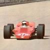
I remember those White winged Chaparral 2e's at Riverside. Many firsts in auto racing were attributed to this genious, named Jim Hall. much of the design still remains shroaded in a cloak of mystery and the clandestine link to General Motors and its connections to aerospace industries. Many autoracing firsts came from that little shop in Midland Texas, where the great man and his wife, who did a lot of the fabrication. still live in reclusion.
Firsts include:
Fibre Plastic monoquoc 'Tub' chassis, 16" forged aluminum racing wheels with special low profile firestone tires. First real racing brakes, first two way telemetry to the pits, first 'dog clutch' auto transmission with locking torque converter.
GM engineer, Frank Winchell, the head of R&D, and Jim Musser, ( Car nuts like you) took note that Jim( MIT grad) was no ordinary weekend racer. This relationship led to special race engines which led to the(ZL1) all aluminum engines, auto transmissions, paddle shifts and most of all the first driver opperated airfoils and the first use of the phraze, 'Aerodynamic balance'.
Chapman's Lotus 49 double chassis car used much of this technology.
Did you know Chapman was an aviation buff also. He left Lotus to build aircraft with Burt Rutan in California, using Irish tax payers money. He died shortly afterwards of a heart attack. Jim Clark and Chapman's relationship had been strained for some time prior to Clark's death, but that is another story.
Anyway, where was I? GM's R&D division aided Jim in exploring' Aerodynamic balance' in Hughes aircraft wind tunnels. Some devices had been used on race cars before, but untill Hall, none had worked in concert before. Musser was working on a mid engine Corvette and was intrigued by Hall's locking torque converter and auto 'dog cam' transmission and incorporated it into the GS11a experimental car. Some Chapparel lap records were never broken. Hap Sharp, Jims partner and Roger Penske started the modern way of making racing big bussiness and both drove early Chapparals. George former could not believe Hall lapping him whilst driving a Lotus 23 in the USRCC series in 64. Jim went on to Can Am with the 6th generation of the car, the best auto racing series of all time, and pulled out when GM did, and was never heard of again till now.
The 2E was the first car to be designed around its aero package with input from Firestone(sound familiar ?) There was a 3rd pedal that drivers such as Phil Hill and Jo Bonier, experienced downforce and g foces of unprecedented proportions, when balancing the front and rear wing lift using NACA type inverted airfoils with struts mounted directly to the cast magnesium suspension uprights. Another first for cars.
Much was known about the mathematics of wing sections from 2nd WW planes, but for race car applications, Jim learned the hard way. The Chapparals should have won every race they entered, but for that damn rear wing. It was under developed and it took a while to understand the dynamic forces acting on this inverted airfoil suspended in space attached to the car's suspension. Remind you of some F1 teams??
Go to the Petroleum Museum in Midland Texas. They have 6 Chapparals. The 2E is made up from parts and the full story is told on video and a wonderfull account from Phill Hill and the driving techniques he employed, using the 3 pedals. One gas one brake and one for the wings.
DOHC, you are right about the under surface been curved as a trade off between L/D ratios for a
given application.
One last thing, in surface effect, the downwash interferes with the relative wind that can not be deflected downward. This increases lift coeficient by up to 20% when the wing is within 10% of its span from the surface. The angle of attack is reduced and so is the drag by the same proportions. Ever see a pelican fly over the water?
---------------------------------------------------------------------------------------------------------------------------
My intention is not to hi-jack the thread here, but I take the liberty of bringing race car downforce in, as an application of flying upside down... 
----------------------------------------------------------------------------------------------------------------------------[/B]
Yeah sure.;)


 How come the net lift does not turn into downforce then
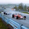


 You didn't say if you wanted to take a shot at my question or if you wanted me to post the answer.


