I'll start by saying this project, or rather idea is driven strictly by ego and has no real necessity driving it. Logically this doesn't need to be done, I simply want to do it. Of course if the results are bound to be horrible, then sense prevails, but where cost or need factor in...they don't (within reason, I'm not rich)
Short version - I have a limited slip differential from a later model BMW I'd like to install in my '81 - because I have it and the car currently has an open diff. For reasons of car-cancer, I need to do a bunch of body work within the trunk area anyway, including a new floor and repairing the stock diff mount. The diff I have is not a bolt-in though I suspect with a minimal of fuss I could machine up 3 new mounts and have it sitting pretty (shock locations are the same, hanger is different). Once I got that far into the plan, the Well, while I'm in here... disease kicked into full gear.
What I'd like to do - stretch both wheel-wells 1" on the inside, shorten the axle shafts the corresponding 1". Rather than fabbing up new mounts, replace the stock steel diff hanger entirely with an aluminium version - and while we're at it, the stock steel trailing arms with aluminium versions.
I'm fairly proficient with SolidWorks and can draw pretty much anything I need to, I can load it, bend it, twist it with COSMOS FEA and if I can't get my head around the machining, I have a very skilled team of people I work with that can. But - and it's a big but - I don't know how to ensure my new parts are strong enough, or conversely not over-built. Sure I'm not building a 1000hp turbo-charged monster but I don't want the diff parting company with the car, nor do I want to end up with an assembly that is heavier than what I started with.
Is there - and I'm ever so hesitant to even ask - a rule of thumb when re-designing steel parts in aluminium? Is there a set of formulas or rules to determine load forces and vectors based on the car's weight or some other factor(s) that I can reasonably determine? Do I need to hire an engineer to do this and live to talk about it?
Go easy now...

Suspension Engineering
Started by
Canuck
, Aug 29 2006 04:37
40 replies to this topic
Advertisement
#2

Greg Locock
-

- 6,494 posts
- Joined: March 03
Member
Posted 29 August 2006 - 06:16
Road use or circuits?
In the past I have said for road use use 5g vertically at the contact patch, and 3 g longitudinally (or say 4 ) and 2g laterally . For circuits, use 3 2 1 respectively. This is the 3 2 1 rule.
So if the corner weight is 460 lb and you are designing for road use then apply 2300 lb to the contact patch in Z, and work out all the stresses everywhere
Then, to be horribly crude add the magnitude of the maximum stresses from the other load cases and you should be well safe.
Those bits are a bit light for a daily driver.
Then you need to find out your material properties.
www.matweb.com
If I were you use 6061 T6 (280 MPa) or, preferably, T4 (145 MPa) and don't weld either at all, and think about stress raisers. If you want to weld it then you'll need a post weld heat treat, and then you'll have to cope with distortion. T4 is preferred due to ductility.
Real suspension parts are forged from aluminum A356, which is better than most billet stuff.
I can't really give you a scale factor for steel->aluminium as the beemer parts are likely to be something moderately nice - good steel is very cheap.
However, I think you could expect a 30% weight saving typically, for the same strength. (Would you bother for less?). Bear in mind that steel is a lot more ductile than aluminium, and we tend to design suspensions so they bend, not break (otherwise we get spanked in court). 12% elongation is a minimum.
Incidentally, knuckles in particualr, and in your case the semitrailing arm (I think) may well be stiffness limited, in which case you may find it tough to get much lighter than a steel part.
#3
Greg Locock
-
- 6,494 posts
- Joined: March 03
Member
Posted 29 August 2006 - 08:06
Here's a calculator that you can use to solve the force distribution in each arm or component. You'll need to do two views of each arm, eg XZ and XY.
http://engineeringre..._page&PAGE_id=3
http://engineeringre..._page&PAGE_id=3
#4
imaginesix
-

- 7,525 posts
- Joined: March 01
Member
Posted 29 August 2006 - 20:55
Great question, and great replies.
Isn't 1G lateral loading a bit low, even for non-aero cars? It's possible to generate more than that in steady-state cornering, with occassional spikes going well above 1?
Also, what is the resultant 'd' from the calculator you linked to? It is distance (inches), but distance of what?
Thanks!
Isn't 1G lateral loading a bit low, even for non-aero cars? It's possible to generate more than that in steady-state cornering, with occassional spikes going well above 1?
Also, what is the resultant 'd' from the calculator you linked to? It is distance (inches), but distance of what?
Thanks!
#5
imaginesix
-
- 7,525 posts
- Joined: March 01
Member
Posted 29 August 2006 - 21:02
OK, 'd' is the shortest distance between a line drawn through the resultant vector and the origin. Kewl.
#6
Greg Locock
-
- 6,494 posts
- Joined: March 03
Member
Posted 29 August 2006 - 22:31
I agree that 3 2 1 is a bit light, but it is accepted practice for non aero cars, many race cars and prototype road cars are designed using 3 2 1. Our solar cars were designed using 3 2 1 and for the most part have survived for 3000-9000 km (admittedly on smooth roads) without suspension cracking.
I suppose they rely on inspection in the case of race cars.
I haven't used that calculator, i just found it yesterday.
I suppose they rely on inspection in the case of race cars.
I haven't used that calculator, i just found it yesterday.
#7
Canuck
-
- 2,413 posts
- Joined: March 05
Member
Posted 30 August 2006 - 00:18
Fantastic Greg - thanks. The car is my daily driver, beat-up, painted-over-rust old 5-series. For some unexplainable reason I like the car despite it's constant need for attention so as I go through and fix the stuff that needs fixing, those little "while you're hear" urges kick in. Long term thoughts - maybe do that 5L V12 swap that Hydra mentioned in the throttle-body discussion, back-half the car as discussed here and have a really, really nice little hotrod that doesn't scream "give me a ticket!"
So if I base the design on 5 4 2, given that it's a daily-driven road car subject to all the manhole covers, potholes and occasional road debris one might expect, I should be within a reasonably safe realm then?
When you say the arms (pic below) are stiffness limited, I'm not really sure what you mean. Do you mean that building an aluminium version with the desired elongation and stiffness factors would end up being the same weight as a steel version?
I'm not sure yet if I can get away with narrowing the track width anyway and if I can't it sort of sends the whole thing in a different direction. I haven't had a chance to measure everything out and see if the arms can also be moved as-is 1", or if the new axle-shaft angles will funciton properly.
Looking at some different materials, 6033-T651 has a Tensile Yield MPa of almost 400 and elongation of 13%, vs. the 6061-T4's of 25%. Even with the greater strength of the 6033, the ductility of the 6061 is the over-riding factor? Of course it may be that 6033 can not be had in the desired shape and size, or may rival AlBeMet for cost for all I know.
#8
imaginesix
-
- 7,525 posts
- Joined: March 01
Member
Posted 30 August 2006 - 02:31
Instead of re-engineering from the ground up, what about reverse-engineering the specific component you are looking to redesign? Take the trailing arms for example; based on material, size and shape determine their yield strength, stiffness, whatever and then apply those figures to aluminium pieces.
Since you're not re-doing the whole chassis there's no point in inventing your own unique set of performance requirements just for those few pieces anyways.
Since you're not re-doing the whole chassis there's no point in inventing your own unique set of performance requirements just for those few pieces anyways.
#9
Greg Locock
-
- 6,494 posts
- Joined: March 03
Member
Posted 30 August 2006 - 02:33
13% would be OK, after all, it's not as if you're going to whinge to the dealer if the thing breaks. I haven't used 6033, might be worth googling for horror stories.
5 4 2 is fine
Your pictures didn't work.
The ratio of young's modulus to density is identical for steel and aluminium, so quite often it is hard to beat steel for stiffness per unit weight. Even a realistic carbon layup (in 3 dimensional strain) won't be that far ahead. That is, if you were to put as much effort into designing the steel part and cost into building it, you might well end up ahead.
A good example of this is small roadwheels - aluminium ones often end up weighing more than steel ones, which actually have better properties in some respects. As the size increases over 15" aluminium usually wins, but the optimum is steel rims on an aluminium spider.
#10
Supercar
-

- 285 posts
- Joined: March 05
Member
Posted 30 August 2006 - 03:22
I know of a case when a guy got a few tumbles in a car when the front knuckle was designed for 1 lateral g and it broke. Also, I once recorded 7 vertical g's at the C.G. when driving on some wavy road. That was a lot of fun! Glad that was not my own car.Originally posted by Greg Locock
I agree that 3 2 1 is a bit light, but it is accepted practice for non aero cars, many race cars and prototype road cars are designed using 3 2 1. Our solar cars were designed using 3 2 1 and for the most part have survived for 3000-9000 km (admittedly on smooth roads) without suspension cracking.

#11
Canuck
-
- 2,413 posts
- Joined: March 05
Member
Posted 30 August 2006 - 03:22
They'd probably work a whole lot better if I actually posted them... 
In the car currently:
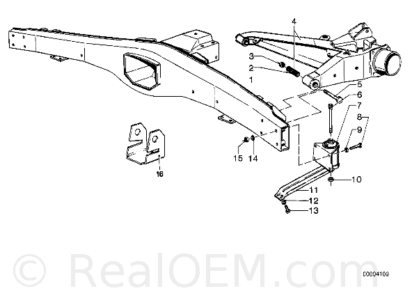
E12 Rear
In the $400 donor car:
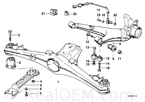
E28 Rear
In looking at the trailing, or semi-trailing (what's the difference?) arms - if I move the inboard leg of the arm (now there's a phrase) towards the outside, effectively making the angle at the hub between the two arms narrower, what effect does this have?
In the car currently:
E12 Rear
In the $400 donor car:
E28 Rear
In looking at the trailing, or semi-trailing (what's the difference?) arms - if I move the inboard leg of the arm (now there's a phrase) towards the outside, effectively making the angle at the hub between the two arms narrower, what effect does this have?
#12
Greg Locock
-
- 6,494 posts
- Joined: March 03
Member
Posted 30 August 2006 - 05:16
Hah,you'll have your work cut out making them stiffer and lighter than that.
Those are almost pure trailing arms, with just a bit of semi to give them a camber curve, and as a free bonus some bump steer, understeer (which you might want, due to the next paragraph).
Moving the inboard bush outboard will reduce the lateral and toe stiffness of the suspension, giving you even more compliance oversteer. That is nasty and inevitable. If it annoys you too much consider adding a toe link behind the wheel, say to the back of the diff, or up to the chassis rail. It'll fight the other arm so you'll have to put some compliance in somewhere, which will bugger your camber stiffness.
Now, the other interesting thing is what happens when braking and accelerating. The wheels will tend to steer, toe in when accelerating, toe out when braking. The latter will make it darty.
Hope you are enjoying all this, this is why it is hard to make refined semi trailing arms. The advantage of a semi trailing arm is that it is cheap, compact, strong and sensible. Not elegant.
#13
Canuck
-
- 2,413 posts
- Joined: March 05
Member
Posted 30 August 2006 - 07:06
A pure trailing arm would have an angle of theta = 0 deg. The E30 trailing arm angle is 15 deg. Some refer to this as the "sweep" angle.
I need some help understanding this still - what is 15' to what?
As suspected I'm in way over my head. But I'm liking the learning.
#14
Engineguy
-

- 989 posts
- Joined: February 01
Member
Posted 30 August 2006 - 09:33
The pure trailing arm (top) pivots on a transverse axis, has NO camber gain.
The not-trailing arm (bottom... yeah... made that up... effectively a swingaxle) pivots on a longitudnal axis, has LOTS of camber gain.
The semi-trailing arm (middle), being in between, has some camber gain

The not-trailing arm (bottom... yeah... made that up... effectively a swingaxle) pivots on a longitudnal axis, has LOTS of camber gain.
The semi-trailing arm (middle), being in between, has some camber gain
#15
Greg Locock
-
- 6,494 posts
- Joined: March 03
Member
Posted 30 August 2006 - 22:35
15 degrees to the y axis of the car.
x is longitudinal (back), y is lateral(right), z is up
x is longitudinal (back), y is lateral(right), z is up
#16
soubriquet
-

- 376 posts
- Joined: June 03
Member
Posted 30 August 2006 - 23:32
FWIW, BMW "fixed" the camber change evils of the M5 by limiting the rear suspension travel to about 5cm.
(you could try grafting in something much nicer, like an Alfetta de Dion)
(you could try grafting in something much nicer, like an Alfetta de Dion)
#17
Powersteer
-

- 2,460 posts
- Joined: September 00
Member
Posted 31 August 2006 - 02:02
Those semi-trailing and trailing arm designs gets very untidy from bushing flexing. Oh, and semi-trailing arm also provides some toe-in.

#18
Canuck
-
- 2,413 posts
- Joined: March 05
Member
Posted 31 August 2006 - 04:37
Thank you folks - I can officially say I learned something new that I had no clue about before. I think, in the interest of both getting it back on the road sooner rather than later, and not spending a boat-load of time and money on something that may only be marginally (or not at all) better, I'll stick to re-engineering the mounts and leave the current dimensions as they are.
In the future, perhaps an SLA design is a better idea. Or not - I still know **** about suspension.
In the future, perhaps an SLA design is a better idea. Or not - I still know **** about suspension.
#19
Greg Locock
-
- 6,494 posts
- Joined: March 03
Member
Posted 31 August 2006 - 22:42
You don't hear many complaints about the BMW 5 series. I'd leave it be. If you want to narrow the track cut and shut the subframe, inboard of the inner suspension bush.
Advertisement
#20
Canuck
-
- 2,413 posts
- Joined: March 05
Member
Posted 01 September 2006 - 00:42
Indeed. This little old beater is easily the best-handling car I've owned, surprised me a fair bit. The seed that started this line of thought is the LSD diff I have. If it was a straight bolt-in swap I wouldn't have travelled down this road (but then I wouldn't have learned a)trailing vs. semi-trailing arm suspension or b)the effects of increased semi-trailing angles on camber and toe.
In looking at the pictures above, would you a) leave everything as is with the open diff, b) modify the stock hanger to accept the LSD diff or c) mount the new hanger and diff (and arms) as an assembly?
In looking at the pictures above, would you a) leave everything as is with the open diff, b) modify the stock hanger to accept the LSD diff or c) mount the new hanger and diff (and arms) as an assembly?
#22
phantom II
-

- 1,784 posts
- Joined: September 05
Member
Posted 01 September 2006 - 03:42
This is a 3 series (open) diff and semi trailing arms on a replica Cobra. The car has a 390 hp 351 Ford. Stock 3 series struts up front with complete 3 series geometory and rubber bushings. Rides real nice. 2400lbs

I use a M3 diff in my roadster with 405 HP. 1800lbs.

I use a M3 diff in my roadster with 405 HP. 1800lbs.
#23
Canuck
-
- 2,413 posts
- Joined: March 05
Member
Posted 02 September 2006 - 08:52
The diff housings are radically different than either of mine. I think I'll stick to measuring up what I have on the car, what I have on the spare car and seeing just how much extra work is involved in making it fit. At the end of the day all I'm after is the LSD (can't say that on too many forums). It would be nice to be able to stuff some bigger rubber under there for looks, but while possible, it's unlikely I'll ever make it to a track-day.
#24
soubriquet
-
- 376 posts
- Joined: June 03
Member
Posted 02 September 2006 - 11:31
I want to get this straight.
Semi-trailing arms give camber change under the following conditions: acceleration, braking, cornering and bump. With wide tyres this geometry arbitrarily changes the contact patch from middle to edge. With all cars except (apparently) BMW, semi trailing arms lead to unpredictable behaviour (unless you count unpredictabilty as predictable). All reviews I've read of semi-trailing arm BMWs stress their tendency to oversteer.
I would very much like to know what makes BMW semi-trailing arms so good. Please enlighten me.
#25
phantom II
-
- 1,784 posts
- Joined: September 05
Member
Posted 02 September 2006 - 12:59
German cars have Mc Pherson struts up front and semi- trailing arms at the back including Porsche, yet all magazines rave about their handling prowess. I think the suspension travel is limited in all cases especially the M cars. 4 people in a Mercedes or BMW throws handling out the window.
Originally posted by soubriquet
I want to get this straight.
Semi-trailing arms give camber change under the following conditions: acceleration, braking, cornering and bump. With wide tyres this geometry arbitrarily changes the contact patch from middle to edge. With all cars except (apparently) BMW, semi trailing arms lead to unpredictable behaviour (unless you count unpredictabilty as predictable). All reviews I've read of semi-trailing arm BMWs stress their tendency to oversteer.
I would very much like to know what makes BMW semi-trailing arms so good. Please enlighten me.
#26
Greg Locock
-
- 6,494 posts
- Joined: March 03
Member
Posted 02 September 2006 - 13:13
So'd I!
Camber thrust from modern radials is only about 5% (that is, if the tire produces say 1 kN of sidethrust per degree of steer, then it'll produce about 50 N of sidethrust per degree of camber). This is less than a quarter of what old crossplies made, so camber thrust is less important than it used to be.
Traditionally you set up a semi trailing arm to have lots of kinematic bump steer (toe in in jounce) to compensate for the compliance oversteer. The problem with that is that your compliance oversteer comes in as soon as the tire starts to bite, whereas you'll only get the compensating kinematic steer after the body has started to roll.
So, the answer is probably that they do something at the front to compensate. I've often found it useful to plot the buildup in forces in the suspension members as a result of a step steer event (Milliken shows some real data on this) - from this you can see what is likely to help to smooth out the response. If you keep the front roll centre low then you can begin to synchronise the body roll and the rear end response, for instance. If you get the body to roll fast enough then you could get the rear suspension to move into jounce before the rear wheels have started to develop sidethrust. Also you've got to consider the relaxation length of the tire - that gives you another few milliseconds.
Also bear in mind that continual development of a second rate architecture can give good results. Look what they do with Macpherson struts, for instance.
#27
soubriquet
-
- 376 posts
- Joined: June 03
Member
Posted 04 September 2006 - 10:05
Thanks very much Greg. I've read this through about 10 times, and another 10 readings should give me some kind of enlightenment.
The first and last paragraphs are perfectly clear to me. I understand entirely who it is that puts food on the family table, but when dealing with McPherson struts, aren't we also inextricably linked with the F word?
I'm no engineer, simply a punter. The nicest road cars I've had were/are a Lancia Beta Coupe and a series of Subaru Liberty/Legacy wagons. Both have struts on all four corners. What am I missing here?
#28
Greg Locock
-
- 6,494 posts
- Joined: March 03
Member
Posted 04 September 2006 - 23:54
"What am I missing here?"
Nothing for road cars with narrowish tires. But if you really want to control the presentation of the contact patch to the road then you have to be able to set your camber gain (deg camber per degree of body roll) at will. MacPherson won't let you do that, except for one corner. Bear in mind that MacP does some things very well, so when you are building a car and start to make the inevitable compromises, a MacP gives you a fair bit of wriggle room (particualrly with budget and weight) that a posher suspension would not. For instance, the cost advantage is so big, I can say, OK I'll accept the MacP, but you have to give me hydrobushes in return. So the customer might end up with a better overall car, even if the suspension engineer is grizzling into his beer because he didn't get his twin wishbones.
The trick is to take a system that works for small cars with narrow tires, and still make it work for big cars with wide tires. In the world of suspension we look at BMW and occasionally think, now why on Earth did they do that? It has usually been instructive to find out why. I think BMW do drop the ball in other areas (to some extent), but their suspension guys seem to have enough clout and nous to make their chassis successful.
#29
Supercar
-
- 285 posts
- Joined: March 05
Member
Posted 05 September 2006 - 01:01
Greg, you seem have figured out some rule of thumb about the MacPherson suspension. Are you saying that in a turn a MacPherson inside front will always have a very unfavorable camber and no large strut inclination, caster or KPI can fix it?Originally posted by Greg Locock
But if you really want to control the presentation of the contact patch to the road then you have to be able to set your camber gain (deg camber per degree of body roll) at will. MacPherson won't let you do that, except for one corner. ...
The trick is to take a system that works for small cars with narrow tires, and still make it work for big cars with wide tires. In the world of suspension we look at BMW and occasionally think, now why on Earth did they do that? It has usually been instructive to find out why. I think BMW do drop the ball in other areas (to some extent), but their suspension guys seem to have enough clout and nous to make their chassis successful.
Touring BMW's, just like Porsches, turn on 3 wheels. But those GT BMW's with really wide front tires stay on all four through the corners and still seem to be going really well! Have you figured out some secret? Is their front geometry just set up for one corner at a time?
#30
Greg Locock
-
- 6,494 posts
- Joined: March 03
Member
Posted 05 September 2006 - 04:58
No, I've only ever worked on a MacP for long enough to unzip the files, had a look at it, and then flicked it over to somebody else (my usual modus operandi).
However just thinking about circuit cars. If they are turning at roughly the same g's on each corner, they'll have the same body roll. So, by stuffing around with static camber enough they can at least set the outer wheel up to give the correct camber compensation for that lattac.
With a bit more hack work you could look at the height of each end of the lateral arm, then you could get some curve into the camber gain curve, and maybe start to get the relationship between the inside and outside wheel right. To be honest I haven't even got a simple spreadsheet model of a MacP, but if you've only got three conditions to tune for (left turn at 1g, right turn at 1g, straight ahead) and are prepared to live with some disgraceful antics in the transition between those 3 conditions, I'd have thought you could do it.
#31
Supercar
-
- 285 posts
- Joined: March 05
Member
Posted 05 September 2006 - 05:10
Thanks, Greg. I need to ressurect my SolidWorks model and play with it a little, and see what I can come up with. Maybe it will not be that ugly afterall.
#32
RDV
-

- 6,765 posts
- Joined: March 02
Member
Posted 05 September 2006 - 05:40
You can have a quite reasonable camber control with a McPherson... the down side is running rather extreme amounts of caster and decoupling the pivot axis from the tower mount... Peugeot tried it with their front double suspension, and Nissan had the "goose neck" arrangement which enabled this.... and they were front wheel drive cars to boot... I wont even talk about the problems you wiil have with powersteering to be able to turn the wheels...
#33
soubriquet
-
- 376 posts
- Joined: June 03
Member
Posted 05 September 2006 - 16:39
Thanks very much Greg and everyone else for your kindness and consideration for an interested amateur  I'm getting too old and too slow to be really critical, so struts do me just fine. The Legacy is fantastic in snow. It is totally predictable, but I can generate a **** kicking power slide at will. The snow in Japan is insane mumble mumble
I'm getting too old and too slow to be really critical, so struts do me just fine. The Legacy is fantastic in snow. It is totally predictable, but I can generate a **** kicking power slide at will. The snow in Japan is insane mumble mumble
#34
Canuck
-
- 2,413 posts
- Joined: March 05
Member
Posted 29 October 2008 - 18:35
Dead Thread revival...
I'm coming back to this thread just as a starting point, primarily because it contains the information for my present setup. I'd recently PM'd Greg about going to A-arms front and rear in the car but abandoned the notion when it occured to me that my ignorance and I were unlikely to better the product that a team of German engineers put together. But...
If we go way, way back, Omar K (who's board name escapes me at the moment) joking suggested replacing the stock power plant with a later V12. That notion has been ticking in away in the back of my mind since that point. Despite dismissing it on a number of occasions for lack of quantifiable purpose, I'm beginning to draw up concepts again, especially in light of the collection of E12s I seem to be amassing.
Think Pro-Touring for lack of a better description - A/C, tunes, a back seat for the kids (or the wife and I ;) ), plenty of power, plenty of rubber, still goes around corners. The V12 is a given unless a late-model M5 V10 falls into my lap for a lot less than the $18k I've seen them for. Not only has a small-block in an E12 already been done (more than once), a small-block has been done so often it's cliche. Which brings us to the subject of my post - the rear end. Earlier in this thread, Greg suggested narrowing the subframe to bring everything to allow for more rubber. I crawled around under the car the other day and started taking measurements but the first thing that crops up is the proximity of the inner trailing arm mounts to the diff mount. Best case scenario, I might manage to narrow the assembly by an inch...maybe. I could mount up a narrowed Ford 9" or GM 12-bolt but those are equally cliche. Thus, we're full circle to the A-arm IRS idea.
In digging around for ideas, I came across some little outfit called Team321 and was looking at this iteration in particular.

My thoughts were to utilize an existing BMW diff from the later E28 and build the rest of the system around that. I'm wondering however about mounting the new subframe to the vehicle. The current system is held in place via rubber bushes from subrame to body and a single one from the top of the diff to a crossmember under the trunk. Would a 3-point system suffice to mount a system similar to the one above? In the stock system, there's also the struts of course, which would be self-contained in the IRS sub-unit, no longer offering connection to the body. I'm thinking additional crossmember(s) are probably prudent, perhaps tied into the bumper mounting area but then I think that the body is resting on the mounts, not the unit hanging by them. Input?
I'm coming back to this thread just as a starting point, primarily because it contains the information for my present setup. I'd recently PM'd Greg about going to A-arms front and rear in the car but abandoned the notion when it occured to me that my ignorance and I were unlikely to better the product that a team of German engineers put together. But...
If we go way, way back, Omar K (who's board name escapes me at the moment) joking suggested replacing the stock power plant with a later V12. That notion has been ticking in away in the back of my mind since that point. Despite dismissing it on a number of occasions for lack of quantifiable purpose, I'm beginning to draw up concepts again, especially in light of the collection of E12s I seem to be amassing.
Think Pro-Touring for lack of a better description - A/C, tunes, a back seat for the kids (or the wife and I ;) ), plenty of power, plenty of rubber, still goes around corners. The V12 is a given unless a late-model M5 V10 falls into my lap for a lot less than the $18k I've seen them for. Not only has a small-block in an E12 already been done (more than once), a small-block has been done so often it's cliche. Which brings us to the subject of my post - the rear end. Earlier in this thread, Greg suggested narrowing the subframe to bring everything to allow for more rubber. I crawled around under the car the other day and started taking measurements but the first thing that crops up is the proximity of the inner trailing arm mounts to the diff mount. Best case scenario, I might manage to narrow the assembly by an inch...maybe. I could mount up a narrowed Ford 9" or GM 12-bolt but those are equally cliche. Thus, we're full circle to the A-arm IRS idea.
In digging around for ideas, I came across some little outfit called Team321 and was looking at this iteration in particular.
My thoughts were to utilize an existing BMW diff from the later E28 and build the rest of the system around that. I'm wondering however about mounting the new subframe to the vehicle. The current system is held in place via rubber bushes from subrame to body and a single one from the top of the diff to a crossmember under the trunk. Would a 3-point system suffice to mount a system similar to the one above? In the stock system, there's also the struts of course, which would be self-contained in the IRS sub-unit, no longer offering connection to the body. I'm thinking additional crossmember(s) are probably prudent, perhaps tied into the bumper mounting area but then I think that the body is resting on the mounts, not the unit hanging by them. Input?
#35
REN_AF1
-

- 75 posts
- Joined: October 08
Member
Posted 29 October 2008 - 20:10
First post, So, Hi to all of you..
Secondly, and absolutely no pun intended at all, (I bodge things up my self)
I wonder what´s the reason for building a suspension with components under more or less pure bending (upper arm)?
I understand that aero considerations might prompt such a contraption, but in a super saloon?
R
Secondly, and absolutely no pun intended at all, (I bodge things up my self)
I wonder what´s the reason for building a suspension with components under more or less pure bending (upper arm)?
I understand that aero considerations might prompt such a contraption, but in a super saloon?
R
#36
Greg Locock
-
- 6,494 posts
- Joined: March 03
Member
Posted 29 October 2008 - 22:15
Lots of cars apply spring loads part way along the arm, bending is not a problem so long as you design for it, and have room. Compared with a normal pushrod setup they've reduced complexity, and aligned the forces a bit better than some arrangements, so that there is less compliance induced bump steer. On the other hand with those lever ratios they are going to need pretty substantial structures and bearings.
Canuck - you very slightly give the impression that I agreed that you couldn't better a BMW semi trailing arm, my attitude was more that for road use it wasn't worth the hassle, the STA works well enough.
Canuck - you very slightly give the impression that I agreed that you couldn't better a BMW semi trailing arm, my attitude was more that for road use it wasn't worth the hassle, the STA works well enough.
#37
Canuck
-
- 2,413 posts
- Joined: March 05
Member
Posted 29 October 2008 - 23:45
Sorry Greg, I only meant to say that in the area of adding more tire under the car, the original solution you proposed wasn't going to work due to the inner arm mounting's proximity to the diff mount.
I picked the IRS in question for no particular reason. In fact it was suggested I go with a lote-model Mustang Cobra IRS and indeed they are reasonably plentiful due to folks pulling them in favour of a straight axle for drag racing. The one or two units I did manage to see in pictures appear to be more complicated than the IRS above. I went with what I "got" first (I wouldn't say I understand it, but I get how I could fit it under my car for the most part).
I'm open to any other input folks might have - I'm certainly outside of my comfort zone and don't have a problem admitting it.
#38
cheapracer
-

- 10,388 posts
- Joined: May 07
Member
Posted 30 October 2008 - 02:48
Originally posted by REN_AF1
First post, So, Hi to all of you..
Secondly, and absolutely no pun intended at all, (I bodge things up my self)
I wonder what´s the reason for building a suspension with components under more or less pure bending (upper arm)?
I understand that aero considerations might prompt such a contraption, but in a super saloon?
R
Packaging, low CG, mass closer to center, ratio's easy to change. As Greg says, the bending and pivot load is a simple engineering problem - use more material!
#39
Greg Locock
-
- 6,494 posts
- Joined: March 03
Member
Posted 30 October 2008 - 09:47
The Cobra IRS is OK, certainly a reasonable bang for your buck, $1500 last time I looked. I'm not fond of the offset spring, and the subframe is a bit of old spaghetti, but, like most rear suspensions, it lets the wheels go up and down.
Advertisement
#40
cheapracer
-
- 10,388 posts
- Joined: May 07
Member
Posted 30 October 2008 - 10:37
Originally posted by Greg Locock
, but, like most rear suspensions, it lets the wheels go up and down.

#41
Canuck
-
- 2,413 posts
- Joined: March 05
Member
Posted 30 October 2008 - 11:11
Looking at fresh pictures of the Cobra unit this morning, it reminded me of what I liked about that 321 design. The overall package height is fairly compact, and it's entirely self-contained. I don't need to add in spring perches or shock mounts or anything of the sort - just figure out the correct way to mount it and it's in. Not so big on the spaghetti.
Did you mean it needs bearings in the upper arms due to the shock linkage/loads? I was wondering about bearings in the arms (as opposed to bushings) anyway - the stock subframe is connected to the car body entirely via rubber mounts. Assuming similar mounting for this IRS, would bearings in the arms have a significant negative impact on NVH (typically speaking)?
Did you mean it needs bearings in the upper arms due to the shock linkage/loads? I was wondering about bearings in the arms (as opposed to bushings) anyway - the stock subframe is connected to the car body entirely via rubber mounts. Assuming similar mounting for this IRS, would bearings in the arms have a significant negative impact on NVH (typically speaking)?


