A while back VAG (Volkswagen Audi Group) launched its W-12 engine. The engine is a four bank design (essenitaly a pair of VR6 engines set at 72 degrees to each other- each VR6 having its cylinders staggered in two rows at 15 degrees). It is a light weight, super compact 6 litre engine available in the Audi A8, VW Phaeton and various Bentleys. Power is from +400bhp to something north of 550bhp depending on model. A sixteen cylinder version in the Bugatti Veyron makes 1030bhp. It seems to have been a rugged and reliable engine.
I read that the crankshaft is rather crowded and in order to make the whole show balance it was necessary to split every big end journal on the crankshaft (a little like the GM 90-degree even-fire V-6 engines). Every rod thus swings on its own separate journal. Ludvigsen's, "The V-12 Engine", has an excellent cross section. To say the least that crank is busy! According to what I've read, the W-12 was made possible by some new bearing technology. In order to make everything fit it was necessary to make the crankshaft a high quality forging with unusually narrow journals. I guess there are some good forges at VAG and Krupp!
The critical issue was the use of ultra-narrow bearings of around 12mm width on the rod big ends. This gave them the ability to leave enough meat in the crank webs so that there was sufficient structure to support the forces generated. I was most intersted by this but have not been able to get any information from VAG. The local importer's engineering support people do not have a clue and their questions to the Germans go unanswered.
What I wanted to know was how it was possible for the bearings of 12mm width (less than half the width those in, say, a Ford Falcon 4.0 litre in-line six) to work in the application. It has been reported that there was some intense research undertaken by VAG's bearing supplier and the result of this enabled them to find a solution. Without this feature, the engine could not have been produced in the form it is.
Is anyone aware of how it is possible to make such narrow bearings survive? I was under the impression that without sufficient width the oil could literally be squeezed right out of there, leading to seizures and failure. Some say this is what used to go wrong with the Ford FE engine in NASCAR, as it had relatively narrow bearings (but not as narrow as the W-12). My knowledge is limited in the area of bearings and how they operate. How would you go about getting such powerful engines to survive with 12mm width bearings? What do you think VAG has done?
Regards
Gerald

Narrow crankshaft journals and bearings
Started by
Gerald Ryan
, Mar 06 2008 18:19
68 replies to this topic
Advertisement
#2

McGuire
-

- 9,218 posts
- Joined: October 03
Member
Posted 07 March 2008 - 11:37
I don't really know, but in looking the thing over it appears the connecting rod big end is very stout for full-width concentricity in order to maximize the journal width that is there.
#3
cheapracer
-

- 10,388 posts
- Joined: May 07
Member
Posted 07 March 2008 - 12:27
As McGuire says, stout conrods and stout crank that will maintain the finer grinding tolerances required. With the more expensive engines such as these, more time can be given to exact the tolerences which can not be acheived with volume production. I am guessing the journals are of reasonable diameter too to aid to give surface area.
Obviously the side clearances and journal end radius add to the picture, I hear the radius is an important area on Ford Clevelands turning big rpm, too small and the localised pressure suffers (oil escapes from the bearing outer edges too rapidly) and too big the oil boils.
The comment about the bearings is interesting from the point of view that, in theory anyway, the bearings don't actually touch the crank while running.
You didnt mention the standard oil specification for these engines, of course this is an area that will help also.
Talking about forging, Joe (insert Jewish surname I forgot) "The Gear Man" (Precision Gears?) I was reading he mentioned that soon crownwheels and pinions will be as forged, no grinding - apparently forging is getting to that fine a tolerance.
#4
Gerald Ryan
-
- 67 posts
- Joined: December 06
Member
Posted 07 March 2008 - 18:55
Cheapracer
The technology to manufacture crownwheels and other gears without machining already exists. It is known as warm forging and was developed by the Bishop Technologies Group in Nth Ryde, Sydney, Australia. The process has been licensed to manfacturers of rack and pinion steering systems for some years. Millions of steering racks have been manufactured by the method. After the forging process no machining of the gear teeth is required.
This process was originally developed in order to allow for the production of steering racks with variable steering ratio. The Bishop VR steering system achieves the ratio change by altering the pressure angle between the rack teeth and the pinion teeth. It is difficult to produce a rack of this type by conventional broaching methods.
The warm forging process gives superior microstructure, better material properties, no machining waste and alows for the rack to be produced with a Y-shape cross section (for better resoultion of steering forces and less friction than round bar rack designs). The process is fast.
It is not surprising that people are looking at warm forging for all sorts of other uses.
Cheers
Gerald
#5
bobqzzi
-

- 360 posts
- Joined: March 05
Member
Posted 08 March 2008 - 02:44
I measured the width of the stock bearings on a VAG 4 cylinder (the rod bearings are the same in everyone back to 83) and it is 19mm wide 48 mm journal and is currently used in an engine making ~55HP cylinder from the factory. Quick and dirty, 2865mm^2 so to equal the area with a 12mm wide bearing it would need to be 76mm in diameter- it's certainly not that big. But, that same 4 cylinder bearing will support 500HP for tens of thousands of miles with no appreciable wear or distress which indicates to me the safety margin for "normal" sized bearings is very large- probably because in a "normal" engine, rod journal spacing is set by bore spacing rather than crank geometry.
It is actually a myth that side clearance affects oil pressure. Many race engines run piston guided rods which have a .25" side clearance
Originally posted by cheapracer
Obviously the side clearances and journal end radius add to the picture, I hear the radius is an important area on Ford Clevelands turning big rpm, too small and the localised pressure suffers (oil escapes from the bearing outer edges too rapidly) and too big the oil boils.
It is actually a myth that side clearance affects oil pressure. Many race engines run piston guided rods which have a .25" side clearance
#6
TDIMeister
-

- 318 posts
- Joined: January 06
Member
Posted 08 March 2008 - 10:29
However, engines with high cylinder counts do not have as high bearing load fluctuations. Engines with 4 or less cylinders are especially bad because there is no overlap between power strokes. Although greatly oversimplified, with the same BMEP and reciprocating inertia, an engine with more cylinders can afford somewhat smaller bearings than one with fewer cylinders (as long as the relationship between cylinder- and main-bearing count still follows).
The W8 is a very interesting engine. It's just like a scaled W12 (2-"VR4" with 72-degrees major bank angle in between minor banks of 15-degrees each). What is very interesting is that it has a "flat" crank, although the crankpins are splayed to achieve an even-firing. I haven't heard one in person but I imagine it sounds very different from a traditional V8 and more like a flat-crank one.
The W8 is a very interesting engine. It's just like a scaled W12 (2-"VR4" with 72-degrees major bank angle in between minor banks of 15-degrees each). What is very interesting is that it has a "flat" crank, although the crankpins are splayed to achieve an even-firing. I haven't heard one in person but I imagine it sounds very different from a traditional V8 and more like a flat-crank one.
#7
TDIMeister
-
- 318 posts
- Joined: January 06
Member
Posted 08 March 2008 - 10:30
Also, starting with the TDI, VW employed 4-layer sputter bearings, and this gave a big increase in specific load-bearing capacity. I believe the W engines use the same technology.
#8
Hans Derbe
-

- 18 posts
- Joined: April 06
New Member
Posted 08 March 2008 - 13:32
In an MTZ article about the second gen W12 engine for the Audi A8 it was mentioned that the rod bearings where made by Taiho and had Al/Sn base with Moly/Sulfate coating. The rod bearings had a widh of 11.6mm and the bigend diameter was 54mm. The weight of the piston(391g) and rod(529g) was reduced and a very stiff block/crank was used.
Hans
Hans
#9
Paul Vanderheijden
-

- 65 posts
- Joined: December 07
Member
Posted 08 March 2008 - 16:47
The idea of using narrow bearings ( and using the resultant additional space to stiffen the crankshaft) has been around for a while. Carlo Abarth used this technique in the late 60s to get his three main bearing, four cylinder engines to run higher RPMs (10,000+).
We too have used connecting rods with narrower journals (with the use of piston guided connecting rods) in current Abarth race motors that our company builds. These are used on the 21mm wide rod jounals, with approx. 0.060 side clearance on each side of the rod. We did go to the extent of DLC coating the connecting rod small ends and the inside cheeks of the piston pin bosses (We already use Sorevi-Bekaert to DLC coat the skirts, ring grooves, piston pins). Excessively high oil pressures are not necessary and would otherwise increase parasitic losses.
While we have not used 12mm wide bearings, we have reduced standard 21mm wide bearings/rods to 18mm with good success. These use a journal diameter of 53.90mm. Likewise we have used special crankshafts utilizing a smaller 50.78mm main journal in order to have a larger journal radius and to reduce bearing speeds at high RPMs.
Paul Vanderheijden
Scuderia Topolino
#10
McGuire
-
- 9,218 posts
- Joined: October 03
Member
Posted 08 March 2008 - 18:04
Originally posted by Hans Derbe
In an MTZ article about the second gen W12 engine for the Audi A8 it was mentioned that the rod bearings where made by Taiho and had Al/Sn base with Moly/Sulfate coating.
Hans
I think the aluminum-tin is probably due to everyone trying to get out of the lead business as much as anything. Current practice is Al-Sn where you can get away with it but a copper-lead etc. backing will still provide greater fatigue resitance IMO. (Taiho also does a coated bearing insert in their own lead-free copper alloy.) The coating appears to be the trick part, imparting some surface toughness while maintaining reasonable embedability. And the coating also allows closing up the clearances a bit with its better film and boundary performance. To me we are back to stiff components on close tolerances to make this work.
Somewhat OT but along these lines... I am told GM is now nearly 100% across the product lines on polymer piston skirt coatings. Tighter clearances are good for everything.
#11
McGuire
-
- 9,218 posts
- Joined: October 03
Member
Posted 08 March 2008 - 18:20
Originally posted by TDIMeister
However, engines with high cylinder counts do not have as high bearing load fluctuations. Engines with 4 or less cylinders are especially bad because there is no overlap between power strokes.
With a four-banger the torque reversals between firing impulses are nearly 150 percent. Soo, the crankshaft is a great big spring that is wound and unwound twice per rotation. Which makes the connecting rods little springs I suppose. So the big spring has four little springs attached along its length, while each little spring is attached to a piston.
#12
J. Edlund
-

- 1,323 posts
- Joined: September 03
Member
Posted 08 March 2008 - 21:33
Placement of the oil drillings is another factor that can improve the capacity of the bearings. For low cost they are often placed in less that ideal positions to make the production simpler.
#13
cheapracer
-
- 10,388 posts
- Joined: May 07
Member
Posted 09 March 2008 - 12:10
Originally posted by bobqzzi
It is actually a myth that side clearance affects oil pressure. Many race engines run piston guided rods which have a .25" side clearance
I was refering specifically to the Ford Cleveland and the info came direct from Dick Johnson's mouth, not a lightwieght when refering to Clevelands.
#14
Gerald Ryan
-
- 67 posts
- Joined: December 06
Member
Posted 10 March 2008 - 18:17
Paul Vanderheijden
How do you go about narrowing standard bearings from 21mm to 18mm?
Do you narrow the con rod big end as well?
Regards
Gerald
How do you go about narrowing standard bearings from 21mm to 18mm?
Do you narrow the con rod big end as well?
Regards
Gerald
#15
TDIMeister
-
- 318 posts
- Joined: January 06
Member
Posted 10 March 2008 - 21:59
I had to make a double take, because I had a former colleague also named Paul Vanderheijden. 
#16
McGuire
-
- 9,218 posts
- Joined: October 03
Member
Posted 27 March 2008 - 10:31
The other thing that comes to mind is that the analytical tools (sims etc) for cranktrains have gotten really good in the past few years.
#17
mcurran07
-

- 5 posts
- Joined: March 08
New Member
Posted 28 March 2008 - 18:28
Originally posted by J. Edlund
Placement of the oil drillings is another factor that can improve the capacity of the bearings. For low cost they are often placed in less that ideal positions to make the production simpler.
Ideally they should be as close as possible but just upstream to the area which receives the minimum oil film thickness and highest loads most of the time. That lies on one side in the lower quadrants of the bearing depending on the engine rotation. Which means they'd make oil passages and the exit in the main caps.
#18
gary76
-

- 114 posts
- Joined: October 05
Member
Posted 14 April 2008 - 10:54
The last correspondent outlined the positioning of the oil passage holes in the bearing journals which has always been my teaching. However I have just been looking at some high rpm 4-stroke engines and find that both the main and big end bearing journals are cross drilled at right angles to the los. This has intrigued me or is this the 'new' thinking? And for what reason?
#19
J. Edlund
-
- 1,323 posts
- Joined: September 03
Member
Posted 14 April 2008 - 23:51
Originally posted by gary76
The last correspondent outlined the positioning of the oil passage holes in the bearing journals which has always been my teaching. However I have just been looking at some high rpm 4-stroke engines and find that both the main and big end bearing journals are cross drilled at right angles to the los. This has intrigued me or is this the 'new' thinking? And for what reason?
What kind of high speed engine has cross drilled crankshafts?
Advertisement
#20
Kevin Johnson
-

- 82 posts
- Joined: November 04
Member
Posted 20 April 2008 - 10:45
Originally posted by Gerald Ryan
Paul Vanderheijden
How do you go about narrowing standard bearings from 21mm to 18mm?
Do you narrow the con rod big end as well?
Regards
Gerald
Going by his info, yes. The side clearance he mentioned, ~.060", is 1.5mm and double that from 18mm is 21mm.
#21
Kevin Johnson
-
- 82 posts
- Joined: November 04
Member
Posted 20 April 2008 - 11:27
Originally posted by cheapracer
quote:
--------------------------------------------------------------------------------
Originally posted by bobqzzi
It is actually a myth that side clearance affects oil pressure. Many race engines run piston guided rods which have a .25" side clearance
--------------------------------------------------------------------------------
I was refering specifically to the Ford Cleveland and the info came direct from Dick Johnson's mouth, not a lightwieght when refering to Clevelands.
My thought is that Dick is correct. Some reflection on the subject reveals that if the journal radius on either side of a rod pair can affect localized pressure so too can the movement of either rod side face to the extrema.
Oil pressure is being used in (at least) two senses in this debate: average and local.
#22
Kevin Johnson
-
- 82 posts
- Joined: November 04
Member
Posted 20 April 2008 - 11:53
Originally posted by J. Edlund
What kind of high speed engine has cross drilled crankshafts?
I looked at some of the cores I use for pattern making. The Mazda BP has cross drilled rod journals. I have a BF/B6 core but in another location. I will try to remember to look at it to see if that was present prior to the bore centers being stretched.
#23
Kevin Johnson
-
- 82 posts
- Joined: November 04
Member
Posted 20 April 2008 - 12:11
Originally posted by gary76
The last correspondent outlined the positioning of the oil passage holes in the bearing journals which has always been my teaching. However I have just been looking at some high rpm 4-stroke engines and find that both the main and big end bearing journals are cross drilled at right angles to the los. This has intrigued me or is this the 'new' thinking? And for what reason?
At least with the BP, which is cross drilled in parallel to a normal to the central axis of the crank*, I am surmizing the orientation is to avoid some ill effects on aerated oil. If the typical location of single outlets was used the stratification of air in the passage would seem to feed the opposing hole a higher percentage of entrained air. Since rod bearing damage can result at 30% entrained air, the local proportion shift could be quite hazardous, particularly if any detonation was encountered. The shift in drilling orientation would appear to deliver the same local percentage of entrained air to both outlets. Safer.
Two outlets deliver a more even pressure gradient.
*Edit: that is not unique enough a description. Add, "and whose drilling midpoint crosses and is perpendicular to an orthogonal of that same normal." Ambiguity -- such is the bane of a natural language.
#24
OO7
-

- 23,612 posts
- Joined: November 04
Member
Posted 29 April 2008 - 17:54
Here is an interesting picture that compares the crank of the W12 with a typical V12: W12 Crank vs V12 Crank
Obi
Obi
#25
Paul Vanderheijden
-
- 65 posts
- Joined: December 07
Member
Posted 03 May 2008 - 02:39
Sorry for the late reply. Been gone for a while.
Regarding narrowing the rod bearings - we made a special jig in which bearings are inserted, much like the big end of a connecting rod. Each side of the bearing is them carefully machined.
As far as the rods go, we simply state to the manufacturer the reduced width required, or if we need to do it to an existing connecting rod then I rough it on the lathe, do the final finish on a Boyar Schultz surface grinder, and then resize the connecting rod on a Sunnen rod hone. In this particular case how much to remove was predicated on the location of the bearing location tang, which we did not wish to move or alter. Of course you need to use special pistons, where the distance between the pin bosses has been reduced so as to now locate the rod on the crank journal.
I have been playing with this for a while. The real issue is whether, with the reduced surface area, there is sufficient hydrodynamic wedge pressure to support the combustion pressures encountered in a competition engine. If we assume that, under normal combustion, the pressure generated is around 900 PSI, and in the case of the Abarth engine the surface area of the piston is 5.26 square inches, then the pressure exerted on the bearing is in the order of 4500+ lbs. This would indicate that the surface area of the bearing must be sufficient to generate a hydrodynamic wedge pressure sufficient to counteract this pressure. As such, the actual supply oil pressure may not be material, as long as there is sufficient flow to support the feed requirements of the various hydrodynamic wedge, rotating bearing interfaces and is also sufficient to carry away the bearing heat, so as to keep the bearing shell within its operational limits.
Our recent tests have shown (supported by current technology in NASCAR ) that the old 10 PSI for every 1000 RPM rule may not be 100% accurate, so long as the flow is sufficient. There are many NASCAR engines that run 500 miles at up to 9200 RPM and do it with no more than 50 lbs of oil pressure, but with sufficient flow.
Speaking of bearings, there are other bearing interfaces that may be adversely affected by lower oil pressures/flow however. One of those that I have experienced is the rocker arm/shaft interface. Unfortunately in older OHV engine designs this type of "boundary lubrication interface", which operates in a oscillating mode, is a concern. It does not develop a hydrodynamic wedge, and uses a "wiping" mechanism to direct oil to the pressure point between the rocker and the shaft. Therefore, it must rely on an adequate oil supply and the inherent lubrication qualities of the oil itself. However the use of higher lift, more aggressive profile camshafts, with the attendant higher rate valve springs, may severely stress this rocker/shaft interface. In such cases extraordinary measures must be taken to ensure that oil can readily flow to the underside of the rocker shaft ( the boundary pressure point). In the case of Abarth OHV engines that includes replacing the rockershaft with one of different metallurgical and surface hardness characteristics (RC 60). The original shaft and rocker were both steel and both of the same hardness (Rc24). Further, radially grooving the shaft, providing an oil pocket on the underside of the shaft and REM polishing and DLC coating the shaft itself in some cases, has led to much improved reliability for this rocker/shaft boundary lubrication interface.
So choosing the right combination of rod bearing width and diameter is not the end of the exercise, as the law of unintended consequences will likely mean that you have to look a little further.
Regards,
Paul Vanderheijden
Hey, the name is not that unusual. There are actually quite a few Vanderheijdens around the world.
#26
Kevin Johnson
-
- 82 posts
- Joined: November 04
Member
Posted 03 May 2008 - 10:52
The reason high oil pressures are used (mainly) is to compress entrained air to a point where the oil behaves more like the idealized fluid envisioned where high flow will suffice.
In an oil system where entrained air is actively and substantially removed then lower oil pressures can be [safely and reliably] employed.
It is important to recognize there are different types of air entrainment. Surface active anti-foam agents are just that -- surface active. Oil manufacturers are in large part not willing to discuss air release values for deeply entrained air. I base this on questioning many of them and receiving a look like I was from the far side of the moon.
Look at the research done in SAE 2004-01-2913 and 2004-01-2915. Deep air entrainment air release times are at least an order of magnitude over typical oil supply cyclic rates.
If you examine some of Porsche's patents the problem is well understood -- they were bitten badly by the 928 and 944.
Dry sumped F1 or NASCAR engines with advanced oil conditioning could survive but I think many readers here are still using or envisioning wetsumps or not seeing a distinction in practice.
#27
McGuire
-
- 9,218 posts
- Joined: October 03
Member
Posted 03 May 2008 - 12:35
Originally posted by Paul Vanderheijden
As such, the actual supply oil pressure may not be material, as long as there is sufficient flow to support the feed requirements of the various hydrodynamic wedge, rotating bearing interfaces and is also sufficient to carry away the bearing heat, so as to keep the bearing shell within its operational limits.
Our recent tests have shown (supported by current technology in NASCAR ) that the old 10 PSI for every 1000 RPM rule may not be 100% accurate, so long as the flow is sufficient. There are many NASCAR engines that run 500 miles at up to 9200 RPM and do it with no more than 50 lbs of oil pressure, but with sufficient flow.
Exactly. Oil pump pressure is simply hydraulic line pressure -- crucial in a control system (like an automatic transmission) but not a first-order deal in lubrication. The real goal is maintaining hydrodynamic and film lubrication where they are needed.
That's why the big end of the VAG rod is so interesting. Across the width of a plain bearing, hydrodynamic pressure is a sort of bell curve, high at the center of the journal and falling off to the sides. If you can raise/flatten out the curve you can use a narrower bearing and journal.
The old 10 psi/1000 rpm "rule of thumb" in performance development was never more than a handy bodge. Flood everything with enough oil and you can often get away with murder.
#28
Kevin Johnson
-
- 82 posts
- Joined: November 04
Member
Posted 03 May 2008 - 12:55
Gosh, just use a gentle parabolic section. You can flatten out your bell curve that way by incrementally shifting/delaying the average transit time for a given molecule.
It would be nice if modern oil systems in production engines were not also control systems. Variable valve timing, hydraulic lifters and so on.
It would be nice if modern oil systems in production engines were not also control systems. Variable valve timing, hydraulic lifters and so on.
#29
Paul Vanderheijden
-
- 65 posts
- Joined: December 07
Member
Posted 03 May 2008 - 15:07
Kevin,
Having read the SAE publications that you cite, as well as others on the effect of windage tray design on surface aeration of oil, it would appear that the even at 50 PSI (3.4 times higher than atmospheric) the percentage of allowable air entrainment may be on the order of 50% for rotating assemblies such as crankshafts, camshafts and counterbalance shafts. That is not to say that 50% should be the design goal. As the percentage of entrained air in oil tracks both RPM and oil temperature, it is important to control free air in oil to a workable amount, as concentration higher than 50% will undoubtedly cause main and rod bearing failures.
From empirical testing at Ford Motor Co. the effects of oil droplets, flung from the rotating assemblies, on the free air percentage of oil in the sump (prior to entering the pump) is inconclusive. Yes, at higher RPM these high speed droplets did cause the oil to foam on the surface of the oil in the sump, but this appeared to have little effect on the entrained air percentage of oil entering the pump. Adding a windage tray to a wet sump appeared according to cited evidence to have little positive effect. Once oil enters the pump no additional air is added to the oil as it traverses the system. With changes in pressure there may be a conversion of some free air to dissolved air and vice-versa. A windage tray, or some other means of controlling the movement of the mass of oil in the pan, does have considerable positive value in terms of ensuring that the oil pump pickup does not become uncovered during high G force situation (Braking, cornering and acceleration - in order of magnitude), or preventing the crankshaft from causing additional aeration from physical contact with the oil in the sump.
The percentage of "dissolved air" in the sump is around 9% by volume. However there is also some amount of free air in the oil as well. Most test specifications dealing with oil aeration assume an 18% air-to-oil volume for dissolved and free air combined. This number also appears to be a good average to shoot for in an oil system design. As I understand it, using Bunsen's coefficient for engine oil, "for every one Bar increase of oil pressure, the oil can take up an extra volume of air equal to 9% of the oil volume". As such at 3.5 Bar (50 PSI) the volume of air-to-oil could be as high as 31.5%. Using the old "hot-rod" formula of 10 PSI oil pressure per 1000 RPM the allowable percentage of air-to oil would equate to 49.6%.
So is this high percentage of air-to-oil what we want? The answer is patently NO. Quite the opposite is what is required, as there is a mechanism within the oil delivery circuit that will negatively impact the percentage of free air. Generally oil routed to the cylinder head will travel via a "sharp edged restrictor". The effect of this type of restrictor is to cause an oil pressure drop in the oil traveling to the upper end. Typically, the pressure drop will be in the order of 40%. Thus if the pressure at the main bearings were 3.5 bar, then the pressure at the rocker shaft (in the case of the Abarth motors that I work with) would be on the order of 2.1 Bar. Whereas at the oil pump, due to the increase in pressure over atmospheric, the percentage of allowable entrained air increased, at the pressure drop to the cylinder head the opposite effect takes place. This means that dissolved air will convert to free air. Combine the additional free air with reduced oil flow (a function of pressure and orifice size), then it is quite feasible for rocker/shaft boundary layer interface in an OHV engine design to be marginalized.
One further consideration would be for engines using SOHC or DOHC designs. The same reduction in oil pressure flow and increased free air percentage, to the upper end oiling, will now affect the formation of the hydrodynamic wedge for the cam bearings. Particularly on start-up, when the oil pressure/flow may be delayed for several seconds, this could have damaging effects. In competition engines with more aggressive camshafts and higher rate valve springs this would give serious cause for further analysis.
One could argue that it would be beneficial to reduce the size of the restriction, thus increasing the pressure/flow to the upper end of the motor. This would have a beneficial effect on reducing the pressure drop, thus lowering the possibility of reconstituting free air from dissolved air in the oil. In addition, the additional oil to the upper end would enhance cooling due to the increased flow. However, this may decrease overall engine oil pressure and yet other measures may have to be taken to return upper end oil to the sump in an efficient manner. All of this points to the use of a dry sump lubrication system, where both the pressure and the flow characteristics of the oil pumping system can be more easily adjusted.
#30
McGuire
-
- 9,218 posts
- Joined: October 03
Member
Posted 03 May 2008 - 15:28
Originally posted by Kevin Johnson
Gosh, just use a gentle parabolic section. You can flatten out your bell curve that way by incrementally shifting/delaying the average transit time for a given molecule.
No, radially the hydrodynamic pressure profile is a nice parabola (approximately) as you have essentially a rolling wedge. But laterally you have a sort-of bell curve, flat on the far ends, as oil is being squeezed out the sides of the bearing shell. And actually, when there is an oil gallery in the journal you have a pair of peaky bell-curve thingies, as hydrodynamic pressure is killed off a the center of the journal in the region of the orifice.
Assemble a new bearing insert and torque it in place with plastigage across the journal. When you disassemble and closely inspect the plastigage across the entire width of the bearing you will see something interesting. This variance in clearance will be even more pronounced with a used bearing insert. It is difficult to maintain precise dimensional control across the full width of the bearing. That is why the W12 connecting rod is so interesting.
#31
Paul Vanderheijden
-
- 65 posts
- Joined: December 07
Member
Posted 03 May 2008 - 16:15
Macquire
DO you then set the clearance on the rod bearings for the flat edge of the Bell Curve ?
Paul
DO you then set the clearance on the rod bearings for the flat edge of the Bell Curve ?
Paul
#32
Paul Vanderheijden
-
- 65 posts
- Joined: December 07
Member
Posted 03 May 2008 - 16:20
Does that intimate that the bearing shell design my not be "flat" across its width. Perhaps the outer edges of the bearing are slightly thicker than the center?
#33
Kevin Johnson
-
- 82 posts
- Joined: November 04
Member
Posted 03 May 2008 - 17:44
Originally posted by Paul Vanderheijden
Kevin,
Having read the SAE publications that you cite, as well as others on the effect of windage tray design on surface aeration of oil, it would appear that the even at 50 PSI (3.4 times higher than atmospheric) the percentage of allowable air entrainment may be on the order of 50% for rotating assemblies such as crankshafts, camshafts and counterbalance shafts. That is not to say that 50% should be the design goal. As the percentage of entrained air in oil tracks both RPM and oil temperature, it is important to control free air in oil to a workable amount, as concentration higher than 50% will undoubtedly cause main and rod bearing failures.
It is nice to communicate with someone that takes the time to read the references. I would love to be local to a more complete technical library with journals. But, back to these articles.
Since we are discussing rod bearings, it is important to note that 30% is the threshold for rod bearing damage and the rate at one bar is already 9%, as you note further down.
Both articles have important confounds with respect to performance engines. For example, on page 6 of 2915, Nemoto et al and Porat and Trapy are cited for determining a range of bubble diameter sizes not affected by engine operation (paraphrased). The authors expand their examination to diameters significantly beyond those (up to 500 millimicrons). In 2913, the engine was fixed and rpms were limited to 3000.
From this it can be deduced that neither article studies an engine itself under various lateral accelerations. It is well known that an engine whose rotating assembly is churning a pool of oil under atmospheric pressure will foam this oil -- this in itself will easily exceed the bubble diameter range being studied in 2915. It is only neccessary to exceed the G-design limit of a given wetsump in question to create this situation. This is deep air entrainment.
With 2913, failure would occur from sustained rpms above 3000 by a vicious cycle. As the rotating assembly strikes the foamed surface oil more heat is generated. More heat expands the bubble diameters and this causes more contact and foaming and so on. The amount of "neat" oil in the sump during normal engine operation is only 2 out of 4 to 5 liters to start with. Allowing for the rate of the pump and the continued foaming, in short order the pump would be drawing in foamed oil. (Many modern engines have their oil pickup openings way above the floor of the pan exacerbating this problem.)
Originally posted by Paul Vanderheijden
...
From empirical testing at Ford Motor Co. the effects of oil droplets, flung from the rotating assemblies, on the free air percentage of oil in the sump (prior to entering the pump) is inconclusive. Yes, at higher RPM these high speed droplets did cause the oil to foam on the surface of the oil in the sump, but this appeared to have little effect on the entrained air percentage of oil entering the pump.
This would certainly change under actual sustained high speed operation. Historically, VW is known to have suffered a spate of engine failures via this mode. The technical fix was a retrofitted windage tray and lowering the oil volume.
Originally posted by Paul Vanderheijden
... Adding a windage tray to a wet sump appeared according to cited evidence to have little positive effect.
I can assure you that is a design issue and that is alluded to in the article. People assume that windage trays are simple matters but they have diametrically opposed technical requirements/tasks in various areas.
Originally posted by Paul Vanderheijden
... Once oil enters the pump no additional air is added to the oil as it traverses the system. With changes in pressure there may be a conversion of some free air to dissolved air and vice-versa. A windage tray, or some other means of controlling the movement of the mass of oil in the pan, does have considerable positive value in terms of ensuring that the oil pump pickup does not become uncovered during high G force situation (Braking, cornering and acceleration - in order of magnitude), or preventing the crankshaft from causing additional aeration from physical contact with the oil in the sump.
The former, hindering pickup uncovering, is more properly termed a baffle -- though certainly baffle and tray designs are often melded. A good distinction can been seen in the steel Toyota 4AGZE sump. When the sump is filled to the stock static oil fill the level reaches to just even with the bottom of the separate tray (often in other engines, like the Ford Zetec E, it just covers the bottom of the "tray" -- the alloy upper sump). In the sump well proper of the 4AGZE the baffle just covers the 2 quarts/liters resident during engine operation. The 4AGZE is incidentally one of the engines with a high pickup (about 25mm off the floor) -- measuring this against oil volume shows that the engine is essentially working off of a 1 quart depth at any given moment. Gives one pause to think, eh?
Originally posted by Paul Vanderheijden
... The percentage of "dissolved air" in the sump is around 9% by volume. However there is also some amount of free air in the oil as well. Most test specifications dealing with oil aeration assume an 18% air-to-oil volume for dissolved and free air combined. This number also appears to be a good average to shoot for in an oil system design. As I understand it, using Bunsen's coefficient for engine oil, "for every one Bar increase of oil pressure, the oil can take up an extra volume of air equal to 9% of the oil volume". As such at 3.5 Bar (50 PSI) the volume of air-to-oil could be as high as 31.5%. Using the old "hot-rod" formula of 10 PSI oil pressure per 1000 RPM the allowable percentage of air-to oil would equate to 49.6%.
As you note below, a mechanism within the oil delivery circuit negatively impacts oil pressure routed to the cylinder head. With the crank, oil pressure above the threshold of the relieve valve is held constant (in most pumps). However as rpms rise above 5000 the centrifugal/centripetal forces acting on the crankshaft and the drilled circuits will increase dramatically. This "mechanism" will encourage stratification and localized areas where air can come back out of solution. Hence the increasing pressure per 1000 rpm requirement of the hot rodder. Great wisdom can be curried from mountains of anecdotal experience, i.e. empirical evidence. Engines are expensive.
Originally posted by Paul Vanderheijden
... So is this high percentage of air-to-oil what we want? The answer is patently NO. Quite the opposite is what is required, as there is a mechanism within the oil delivery circuit that will negatively impact the percentage of free air. Generally oil routed to the cylinder head will travel via a "sharp edged restrictor". The effect of this type of restrictor is to cause an oil pressure drop in the oil traveling to the upper end. Typically, the pressure drop will be in the order of 40%. Thus if the pressure at the main bearings were 3.5 bar, then the pressure at the rocker shaft (in the case of the Abarth motors that I work with) would be on the order of 2.1 Bar. Whereas at the oil pump, due to the increase in pressure over atmospheric, the percentage of allowable entrained air increased, at the pressure drop to the cylinder head the opposite effect takes place. This means that dissolved air will convert to free air. Combine the additional free air with reduced oil flow (a function of pressure and orifice size), then it is quite feasible for rocker/shaft boundary layer interface in an OHV engine design to be marginalized.
One further consideration would be for engines using SOHC or DOHC designs. The same reduction in oil pressure flow and increased free air percentage, to the upper end oiling, will now affect the formation of the hydrodynamic wedge for the cam bearings. Particularly on start-up, when the oil pressure/flow may be delayed for several seconds, this could have damaging effects. In competition engines with more aggressive camshafts and higher rate valve springs this would give serious cause for further analysis.
One could argue that it would be beneficial to reduce the size of the restriction, thus increasing the pressure/flow to the upper end of the motor. This would have a beneficial effect on reducing the pressure drop, thus lowering the possibility of reconstituting free air from dissolved air in the oil. In addition, the additional oil to the upper end would enhance cooling due to the increased flow. However, this may decrease overall engine oil pressure and yet other measures may have to be taken to return upper end oil to the sump in an efficient manner. All of this points to the use of a dry sump lubrication system, where both the pressure and the flow characteristics of the oil pumping system can be more easily adjusted.
Just put a secondary oil pump off the end of the cam fed by the first. Pick what pressure you desire for the valve train. Surely that has been patented.
#34
Kevin Johnson
-
- 82 posts
- Joined: November 04
Member
Posted 03 May 2008 - 17:52
Originally posted by Paul Vanderheijden
Does that intimate that the bearing shell design my not be "flat" across its width. Perhaps the outer edges of the bearing are slightly thicker than the center?
Correctomundo.
As I meandered about my yard this morning I was struck that perhaps a "fractalized" philosophy could help. If you line that design with tiny parabolic grooves this might allow you to tune the bearing. The foci of the parabolae might benefit from variation.
Gosh, look at all the money spent on laser etch-a-sketching cylinder walls. Don't the bearing folks deserve some more time on the super computers?

#35
Paul Vanderheijden
-
- 65 posts
- Joined: December 07
Member
Posted 03 May 2008 - 23:34
Kevin,
This is the current wet sump arrangement that is used on the Abarth motor.

The cast sump is divided into two halves, with a full windage tray that lies at the joining line of the top and bottom halves. Sump capacity is nominally 5 litres, of which approx 4 litres is carried below the windage tray during engine running. The oil level is roughly .5 inch below the windage tray. The pump pick-up is mesh covered with a 7 square inch surface area, mounted approx. .250 inch above the bottom of the sump and surrounded on all four sides with cast fences to control oil flow around the pick up. In this design much of the 4 liters below the windage tray can be considered as "neat" oil capacity.
By restricting the oil level to below the windage tray, the oil control is very good even in long sweeping corners when it would most likely ride up on the side of the block.
The oil pump, in the standard wet sump location pumps the oil directly out of the block and to a rather complicated oil filter arrangement. This has both a thermostatic and an oil pressure bypass. Until oil reaches a preset operating temperature (180F) it is routed through the filter and then directly to the main oil galley. Once it reaches 180 degrees the oil is routed to an external cooler, after going through the filter, and then to the main oil galley. This has proven to be a very good combination of oil pickup management and filter control.

As such, the generation of "super bubbles" as a result of crankshaft oil churning is fairly well eliminated.
I do like your concept of a separate oil supply for the upper end of the motor. Certainly in an overhead cam design it might be fairly easy to accomplish. In an OHV design one would have to be much more innovative, but it does provide some interesting options for upper end oiling, including oil cooling of components such as the valve springs. I suppose if you are using a dry sump system, then it might not be too difficult to run a second pressure pump section just for this purpose.
I have another separate issue with regard to engine cooling, that I will start a new thread on, and I would love to hear your assessment.
Regards,
Paul
This is the current wet sump arrangement that is used on the Abarth motor.
The cast sump is divided into two halves, with a full windage tray that lies at the joining line of the top and bottom halves. Sump capacity is nominally 5 litres, of which approx 4 litres is carried below the windage tray during engine running. The oil level is roughly .5 inch below the windage tray. The pump pick-up is mesh covered with a 7 square inch surface area, mounted approx. .250 inch above the bottom of the sump and surrounded on all four sides with cast fences to control oil flow around the pick up. In this design much of the 4 liters below the windage tray can be considered as "neat" oil capacity.
By restricting the oil level to below the windage tray, the oil control is very good even in long sweeping corners when it would most likely ride up on the side of the block.
The oil pump, in the standard wet sump location pumps the oil directly out of the block and to a rather complicated oil filter arrangement. This has both a thermostatic and an oil pressure bypass. Until oil reaches a preset operating temperature (180F) it is routed through the filter and then directly to the main oil galley. Once it reaches 180 degrees the oil is routed to an external cooler, after going through the filter, and then to the main oil galley. This has proven to be a very good combination of oil pickup management and filter control.
As such, the generation of "super bubbles" as a result of crankshaft oil churning is fairly well eliminated.
I do like your concept of a separate oil supply for the upper end of the motor. Certainly in an overhead cam design it might be fairly easy to accomplish. In an OHV design one would have to be much more innovative, but it does provide some interesting options for upper end oiling, including oil cooling of components such as the valve springs. I suppose if you are using a dry sump system, then it might not be too difficult to run a second pressure pump section just for this purpose.
I have another separate issue with regard to engine cooling, that I will start a new thread on, and I would love to hear your assessment.
Regards,
Paul
#36
Kevin Johnson
-
- 82 posts
- Joined: November 04
Member
Posted 04 May 2008 - 11:58
Originally posted by Paul Vanderheijden
Kevin,
This is the current wet sump arrangement that is used on the Abarth motor.
The cast sump is divided into two halves, with a full windage tray that lies at the joining line of the top and bottom halves. Sump capacity is nominally 5 litres, of which approx 4 litres is carried below the windage tray during engine running. The oil level is roughly .5 inch below the windage tray. The pump pick-up is mesh covered with a 7 square inch surface area, mounted approx. .250 inch above the bottom of the sump and surrounded on all four sides with cast fences to control oil flow around the pick up. In this design much of the 4 liters below the windage tray can be considered as "neat" oil capacity.
By restricting the oil level to below the windage tray, the oil control is very good even in long sweeping corners when it would most likely ride up on the side of the block.
PBS is certainly in agreement with me about the fundamental issues:
http://www.mirafiori...bs/pbssohc.html
Fiat X 1/9 132 engjne PBS Engineering
“The stock oil system in these engines is quite adequate for completely stock cars, but high performance modifications and very hard driving can cause problems with oil control. The stock oil pressure is about 55psi at high r.p.m. For racing, we recommend about 10psi per thousand r.p.m. PBS offers a high pressure oil relief spring which raises the maximum output pressure of the stock oil pump to about 85psi.”
...
“Cars which are equipped with wide wheels and tires, and are driven hard in corners, need special attention to the oil control system. If the oil moves away from the oil pump pickup during cornering, and an air bubble is picked up by the pump, the rod bearings can be destroyed almost instantly. PBS sells a special, sheet steel oil baffle which fits between the oil pan and the block. This is available either for use with the stock oil pump, or in a version suitable for use with a dry sump system. The purpose of the extra oil baffle is to keep the oil from climbing the walls and getting picked up by the crankshaft. We have seen as much as a 40bhp power loss, in dyno testing* a racing engine, when the oil got out of control and was churned up by the crankshaft. By controlling the oil in the pan with this baffle, the oil level can safely be run higher than normal, with a wet sump system. We recommend running one extra quart of oil with this baffle and being sure to maintain the higher level between oil changes. When installing this baffle, we use two 128 pan gaskets, one on each side of the baffle. 128 pan gaskets are thicker than X1/9 pan gaskets and provide a better seal. Longer pan bolts are also recommended to allow for the extra gasket and baffle thickness.”
* I know there are tilting dynos for both engines and chassis -- I don't know yet if dyno tech has allowed the introduction of vectors that are not in a plane coincident to the central axis of the crank.
The difficulty comes with increasing G forces and the resulting angle of repose of the oil in both the sump bounded by the tray and the returning oil -- hence the diametric opposition of some tray requirements. Dave Bean, in his English Ford Racing Engine catalog, has a nice discussion about the general issue with regards to swinging pickups and baffles. This difficulty is what lead to the problems with the Porsche 928 wet sumped engine at speed. If you examine the early 928 sump it has a beautiful and well thought out baffling system and tray. A contemporary cognate with these issues would be the Toyota 1ZZ and 2ZZ in the Spyder or Elise chassis. BMW deals with elements of the problem by employing dual pumps. Chrysler wanted to do this with the Viper but it was deemed too expensive.
I think it is possible with modern technology to design an (expensive) active wet sump that could at least equal a dry sump. My guess is that it would be promptly declared illegal by various racing organizations. Lots of cool stuff in F1 meets the same fate. A pity.
Originally posted by Paul Vanderheijden
...
The oil pump, in the standard wet sump location pumps the oil directly out of the block and to a rather complicated oil filter arrangement. This has both a thermostatic and an oil pressure bypass. Until oil reaches a preset operating temperature (180F) it is routed through the filter and then directly to the main oil galley. Once it reaches 180 degrees the oil is routed to an external cooler, after going through the filter, and then to the main oil galley. This has proven to be a very good combination of oil pickup management and filter control.
As such, the generation of "super bubbles" as a result of crankshaft oil churning is fairly well eliminated.
I like the oil filter setup. It would have little effect on saturated dissolved air in oil solutions, however.
Originally posted by Paul Vanderheijden
I do like your concept of a separate oil supply for the upper end of the motor. Certainly in an overhead cam design it might be fairly easy to accomplish. In an OHV design one would have to be much more innovative, ...
Nah, just treat the cam as a jackshaft. Pretty straight forward. Gosh, look at what Renault did with the water pump in the Sierra engine in the R5 ("Le Car") or the R16 alloy engine.
#37
McGuire
-
- 9,218 posts
- Joined: October 03
Member
Posted 04 May 2008 - 12:42
Originally posted by Paul Vanderheijden
Does that intimate that the bearing shell design my not be "flat" across its width. Perhaps the outer edges of the bearing are slightly thicker than the center?
No, more the opposite. if you take a fresh set of inserts out of the box and carefully measure them with a ball mike, you will find variations in thickness approaching .0001" at various points around the shells, and in a semi-reliable pattern (though not that one). You may also find thickness variations of .0001" to perhaps .0003-4" (for a large main thrust bearing) among bearing pairs, which can be useful in optimizing clearances by moving the vertical stackups around. (Mating the thickest shell to the smallest journal etc.)
Of course, you will also find that the two shells when mated together have a circumference of greater than 360 degrees. As we know, that is to provide around .001" of bearing "crush" when the shells are assembled in their bore. It's an interference fit where the soft shell material is "flowed" into the cap and saddle. (Or, how a good engine man can read as much from the back of the insert as from the front. When a bearing spins, it's due to something wrong on the backside, not the rolling side.) And once the shells have been installed and torqued, and especially once they have been run, their thicknesses at any point will now be all over the place.
The fitted new clearance varies slightly across the width of the shell because the cap and saddle are less than infinitely rigid. There is greater clamping force in the center of the bearing around the bolt. It's not very much in most cases, but it is enough to discern with the plastigage if you look closely enough.
#38
McGuire
-
- 9,218 posts
- Joined: October 03
Member
Posted 04 May 2008 - 13:07
Originally posted by Kevin Johnson
It would be nice if modern oil systems in production engines were not also control systems. Variable valve timing, hydraulic lifters and so on.
Well, they really aren't control systems. Not very good ones anyway. The closest example of oil pump circuit as control system we can think of is the fuel pump switch. Unless there is enough oil pressure to move a ball against a spring and close the switch contacts the engine is not going to run. Now there is a discrete binary control function. But beyond that things get pretty fuzzy, problem being that an oil pump is a constant-displacement device. Its volume is proportional to speed, but its pressure not really.
In the case of an automatic transmission, the whole thing runs on pressure, but to get any usefully precise control authority we will need vacuum modulators, throttle valves, fly governors etc and so forth. Of course in modern times we operate all the shift valves with solenoids. And with VVT we can operate the mechanism with hydraulic power, but to do truly useful things with it we will generally need an electo-hydraulic valve, typically commanded by the engine's CPU. A hydraulic lifter really has no pressure-related control function. It is designed on purpose so that the oil pressure can vary up and down 50 percent or more and it will still work exactly the same.
#39
Kevin Johnson
-
- 82 posts
- Joined: November 04
Member
Posted 04 May 2008 - 13:45
Originally posted by McGuire
No, more the opposite. if you take a fresh set of inserts out of the box and carefully measure them with a ball mike, you will find variations in thickness approaching .0001" at various points around the shells, and in a semi-reliable pattern (though not that one). You may also find thickness variations of .0001" to perhaps .0003-4" (for a large main thrust bearing) among bearing pairs, which can be useful in optimizing clearances by moving the vertical stackups around. (Mating the thickest shell to the smallest journal etc.)
Of course, you will also find that the two shells when mated together have a circumference of greater than 360 degrees. As we know, that is to provide around .001" of bearing "crush" when the shells are assembled in their bore. It's an interference fit where the soft shell material is "flowed" into the cap and saddle. (Or, how a good engine man can read as much from the back of the insert as from the front. When a bearing spins, it's due to something wrong on the backside, not the rolling side.) And once the shells have been installed and torqued, and especially once they have been run, their thicknesses at any point will now be all over the place.
The fitted new clearance varies slightly across the width of the shell because the cap and saddle are less than infinitely rigid. There is greater clamping force in the center of the bearing around the bolt. It's not very much in most cases, but it is enough to discern with the plastigage if you look closely enough.
Many companies take advantage of these variations in thickness during initial assembly.
When I replied to Paul (apparently referring to you rather than my reply to you) it was to deliberately make the bearing cross section parabolic. In that way you can contrive to have one mathematical distribution curve work against another. It seems, though, that this would require machining tolerances more commonly found in hydraulic lifters than bearing inserts. Imagining costs nothing, however.

Advertisement
#40
Kevin Johnson
-
- 82 posts
- Joined: November 04
Member
Posted 04 May 2008 - 14:11
Originally posted by McGuire
Well, they really aren't control systems. Not very good ones anyway. The closest example of oil pump circuit as control system we can think of is the fuel pump switch. Unless there is enough oil pressure to move a ball against a spring and close the switch contacts the engine is not going to run. Now there is a discrete binary control function. But beyond that things get pretty fuzzy, problem being that an oil pump is a constant-displacement device. Its volume is proportional to speed, but its pressure not really.
In the case of an automatic transmission, the whole thing runs on pressure, but to get any usefully precise control authority we will need vacuum modulators, throttle valves, fly governors etc and so forth. Of course in modern times we operate all the shift valves with solenoids. And with VVT we can operate the mechanism with hydraulic power, but to do truly useful things with it we will generally need an electo-hydraulic valve, typically commanded by the engine's CPU. A hydraulic lifter really has no pressure-related control function. It is designed on purpose so that the oil pressure can vary up and down 50 percent or more and it will still work exactly the same.
No problem: here is an example of a solution to a discrete binary function which is attempted by the lubricating circuit and aforesaid due to the fact that the previous iteration goes wrong trying to achieve the simultaneity expected of an ideal fluid. Why? Air, me thinks.
From the description section of United States Patent 6742486:
...
From German Patent Document DE 196 23 818 A1, a system of the above-mentioned type is known in which the camshaft adjuster can be locked in an end position by means of a locking element arranged in the rotor of the camshaft adjuster. By way of hydraulic lines leading to the locking element, the locking element can be changed from its locking position into an unlocked position. When the camshaft adjuster is unlocked, as a result of the hydraulic adjustment of the rotor relative to the driving wheel of the camshaft, the timing of the inlet and outlet valves respectively can be changed as desired. The system illustrated in German Patent Document DE 196 23 818 A1 is constructed such that the pressure admission to the hydraulic chambers, by means of which the adjustment of the rotor with respect to the stator of the camshaft adjuster takes place, and the hydraulic pressure admission for unlocking the locking pin takes place in parallel. However, this does not always ensure that the locking of the adjusting unit is released first before the rotor is changed into an adjusting position by the pressure chambers or hydraulic chambers constructed in the adjusting unit. As a result, operating conditions may occur in which the adjusting unit does not operate in a reliable manner.
...
Inventors:Palesch, Edwin (Lenningen, DE)
Maier, Martin (Hechingen, DE)
Rein, Gordon (Ulm, DE)
Application Number:10/169672 Filing Date:12/10/2002 Publication Date:06/01/2004 View Patent Images:Images are available in PDF form when logged in. To view PDFs, Login or Create Account (Free!) Referenced by:View patents that cite this patent Export Citation:Click for automatic bibliography generation Assignee:PORSCHE AG (DE)
HYDRAULIK RING GMBH (DE)
Primary Class:123/90.170 Other Classes:123/90.310, 123/90.150 International Classes:F01L1/344; F01L1/34 Field of Search:123/90.31, 123/90.17, 123/90.12, 123/90.15 US Patent References:4858572 Shirai et al. 123/90.12 Device for adjusting an angular phase difference between two elements
5816204 Moriya et al. 123/90.17 Variable valve timing mechanism for internal combustion engine
6006708 Ken et al. 123/90.17 Valve timing controlling apparatus for internal combustion engine
6477996 Ogawa 123/90.15 Variable valve timing system
Foreign References:DE19825287
DE19903624
EP0857858 Valve timing control device
Primary Examiner:Denion, Thomas Assistant Examiner:Eshete, Zelalem Attorney, Agent or Firm:Crowell & Moring LLP
#41
Pro-1
-

- 3 posts
- Joined: September 08
New Member
Posted 07 September 2008 - 18:05
Hi all.
I´ve found very interesting this post about the "narrow journal W engines". We are now in the process of selecting an engine for a race car and the choice is between the VW W8 4.0L and a V6 (a Nissan 350Z, stroked to 3.9-4.0L). Room is just not enough for a "conventional" V8.
My main concerns about the W8 are indeed the rods and bearings, so narrow. Even small ports wouldn´t be a problem because 400HP and 8000rpm would be enough to be competitive but reliability for this numbers with a 13mm rod and 11.6mm bearing really makes me upset.
I see the W12 has been developed up to 650HP with turbos so it seems bearings can spread that pressure over their surface quite well and I think that with high performance bolts, 8-8500rpm wouldn´t be an issue.
Does anybody know of a successful race application of this engine (W8)?.
Any positive or negative feedback about this?.
Thanks!
#42
Kevin Johnson
-
- 82 posts
- Joined: November 04
Member
Posted 07 September 2008 - 18:25
Seems like the Nissan motor is going to have loads more aftermarket support and already developed parts.
#43
Pro-1
-
- 3 posts
- Joined: September 08
New Member
Posted 07 September 2008 - 18:35
Thanks for the reply Kevin.
That´s obvious indeed. Anyway all performance parts will be custom made. The point here is whether the W8 will be reliable for the 400HP and 8000rpm so we can "use" the advantage of the 8 cylinders instead of 6. Stroking the V6 to 4.0L will make it quite torquey but I doubt we could reach more than 370Hp due to the small valves, ports and small rod ratio for high rpm. Needless to say that is always nice to win with something "different" from the rest...
That´s obvious indeed. Anyway all performance parts will be custom made. The point here is whether the W8 will be reliable for the 400HP and 8000rpm so we can "use" the advantage of the 8 cylinders instead of 6. Stroking the V6 to 4.0L will make it quite torquey but I doubt we could reach more than 370Hp due to the small valves, ports and small rod ratio for high rpm. Needless to say that is always nice to win with something "different" from the rest...
#44
TDIMeister
-
- 318 posts
- Joined: January 06
Member
Posted 07 September 2008 - 18:50
Notwithstanding that I'm something of a VW fan, this is a hard thing to say: I agree with Kevin to go with the V6. Splayed crankpins reduce the strength and stiffness of the crankshaft, which could be one consideration. The V6 is more compact, most likely lighter, and easier to tune for gas flow with equal length ports and 3-cylinder groupings. The W8 is undersquare (0.93 bore/stroke -- which limits valve area); has a not great 1.9 con rod L/R ratio (affects 2-order vibration); and has a long stroke of 90.2mm, which means that at your targeted 8500 RPM, you will be running a very high 25.6m/s mean piston speed. For all this evidence, the overwhelming conclusion is to advise against the W8...
Although not directly related to bearing dimensions, the following should be of interest:
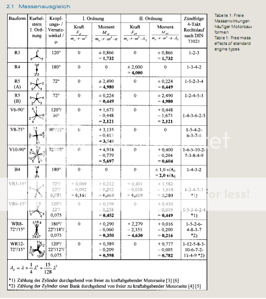
Although not directly related to bearing dimensions, the following should be of interest:
#45
TDIMeister
-
- 318 posts
- Joined: January 06
Member
Posted 07 September 2008 - 18:55
In fairness 60-degree V6s also used splayed crankpins, so I'll call this factor a wash.
#46
Pro-1
-
- 3 posts
- Joined: September 08
New Member
Posted 07 September 2008 - 19:01
thanks a lot for the info TDImeister!.
You say 1.9 rod L/R which is not probably right. I doubt this engine have anything under 3.3 actually, that´s something like a 150mm long rod minimum.
About the mean piston speed: 25m/seg is ok for a race engine at rpm limit, that wouldn´t be a problem.
You are right about tuning the engine with perfectly equal ports. That´s a big point for sure for the V6.
Thanks.
#47
-RM-
-

- 149 posts
- Joined: January 02
Member
Posted 07 September 2008 - 19:45
IES claims 500 hp out of their 3.4L Maxima based engine with a 44 mm restrictor.
#48
TDIMeister
-
- 318 posts
- Joined: January 06
Member
Posted 07 September 2008 - 19:58
L/R is measured differently by different people. I use the definition of rod length / full-stroke (yes, the "R" is misleading). Others take the rod length / stroke radius or its inverse. So by the other definition, it's 3.803 or 0.263 (the con rod length is 171.5mm, and stroke 90.2mm, common with the W12).
The mean piston speed may be fine for dedicated race engines but still high IMO for a production-base. I think the long (in absolute terms) and slender con rod will be problematic here, and with such a L/R ratio, the second order forces which which are in the same direction as the the first order at TDC will make for high G-forces and stresses on the rod.
On the oversquare V6 you can get more valve area per swept volume than you can with the undersquare W8, and you also have a better combustion chamber shape because with the VR engines, the shared cylinder head deck between 15-deg minor banks is inevitably not perpendicular to the cylinder axes.
#49
Kevin Johnson
-
- 82 posts
- Joined: November 04
Member
Posted 07 September 2008 - 21:07
Originally posted by Pro-1
Thanks for the reply Kevin.
That´s obvious indeed. Anyway all performance parts will be custom made. The point here is whether the W8 will be reliable for the 400HP and 8000rpm so we can "use" the advantage of the 8 cylinders instead of 6. Stroking the V6 to 4.0L will make it quite torquey but I doubt we could reach more than 370Hp due to the small valves, ports and small rod ratio for high rpm. Needless to say that is always nice to win with something "different" from the rest...
http://en.wikipedia....issan_VQ_engine
Try tweaking this one; with all the money you save on custom parts you can buy a Bentley Turbo R as a tow vehicle:
The VQ37VHR is a 3.7 L (3696 cc) engine with an increased compression ratio of 11.0:1, with a 95.5 mm bore and 86 mm stroke, while redline remains at 7500 RPM. It is rated at 333 PS (328 hp/245 kW) at 7,000 RPM and 37 kg·m (363 N·m/268 ft·lbf) at 5,200 RPM.
#50
Ray Bell
-

- 82,368 posts
- Joined: December 99
Member
Posted 08 September 2008 - 20:57
While on this subject, has anyone got any idea about using narrow rods on wide journals?
I know there are rods which are 'piston guided'... I don't know to what extent. But with the modern shift to tiny big ends, many cranks can be ground down to the journal size, but the journal width is often too great.
Has anyone ever addressed this issue? I mean found an answer to it without replacing the crank?


