Jump to content


Photo
- - - - -

Tilting-valves vs reed-valves and rotary-valves


  • Please log in to reply
24 replies to this topic

#1 manolis

manolis
  • Member

  • 935 posts
  • Joined: May 03

Posted 21 July 2013 - 04:27

Here:

Posted Image

Posted Image

is a 2-stroke opposed-piston spark-ignition cross-uniflow perfectly-rid-of-vibrations high-revving free-breathing-with-additional-time-for-the-combustion compact and lightweight engine.

It fits to micro-engine applications (RC engines etc) and to normal size special applications.


During the compression stroke the vacuum inside the scavenging pumps (at the two sides of the engine) causes the flow of mixture from the crankcase.
During the expansion stroke, the opening at the bottom of the piston is closed by the tilting valve (the crankcase is sealed from the scavenging pump).
The mixture in the two scavenging pumps is compressed waiting the piston to allow the communication of the scavenging pump with the combustion chamber.
The thrust loads are taken at the wrist-pin end of each piston wherein the cylinder and the piston are substantially cooler (more reliable operation with lower lube consumption).
With the "combustion" side of the piston being rid of thrust loads, and with the wrist pin not hiding the backside of the piston crown, the pistons and the cylinder run cooler and more reliable. The only duty that remains for the "combustion" side of the pistons to fulfil is to seal the combustion chamber.
For more: pattakon tilting valve

Can you see any advantages of the reed-valves and of the rotary-valves over the tilting-valves?

Thanks
Manolis Pattakos

Advertisement

#2 gruntguru

gruntguru
  • Member

  • 7,642 posts
  • Joined: January 09

Posted 22 July 2013 - 00:02

Nope. Looks good to me.

#3 Greg Locock

Greg Locock
  • Member

  • 6,363 posts
  • Joined: March 03

Posted 22 July 2013 - 02:47

Nope. Looks good to me.


I don't like the wiping action of the seal on the valve as it engages with the lip of the piston. If it is a seal. Other than that the design looks very neat. Sadly the worldwide market for 2 strokes has pretty much dried up!

#4 desmo

desmo
  • Tech Forum Host

  • 29,500 posts
  • Joined: January 00

Posted 22 July 2013 - 03:06

I think they're still common in Asia and the Third World aren't they? You can still see a lot of 2-stroke scooters, Apes and the like on the road in Italy.

#5 gruntguru

gruntguru
  • Member

  • 7,642 posts
  • Joined: January 09

Posted 22 July 2013 - 04:29

2 strokes still dominate the extreme bottom and top ends of the IC engine capacity scale. There may be potential for 2 strokes to re-emerge somewhere in between as diesel range extenders.

#6 MatsNorway

MatsNorway
  • Member

  • 2,822 posts
  • Joined: December 09

Posted 22 July 2013 - 06:56

There is outboard two strokes still.

http://www.yamahaout...e-HPDI/overview

Note the odd 76 degree Vee.

Edited by MatsNorway, 22 July 2013 - 07:18.


#7 manolis

manolis
  • Member

  • 935 posts
  • Joined: May 03

Posted 22 July 2013 - 14:57

I don't like the wiping action of the seal on the valve as it engages with the lip of the piston. If it is a seal. Other than that the design looks very neat. Sadly the worldwide market for 2 strokes has pretty much dried up!


Greg Locock,

The tilting valve is integral with the connecting rod; both, the con-rod and the tilting valve, pivot about the wrist pin axis.
There is no contact on the lip of the piston; instead, there is a tiny gap (say 0.05mm) between the tilting valve edge and the piston lip (no wear, nor friction).
The small pressure difference between the space underside the piston crown (i.e. the crankcase) and the space in the scavenging pump needs not a better sealing.

Thanks
Manolis Pattakos


#8 rgsuspsa

rgsuspsa
  • Member

  • 232 posts
  • Joined: November 03

Posted 24 July 2013 - 19:35

Here:

Posted Image

Posted Image

is a 2-stroke opposed-piston spark-ignition cross-uniflow perfectly-rid-of-vibrations high-revving free-breathing-with-additional-time-for-the-combustion compact and lightweight engine.

It fits to micro-engine applications (RC engines etc) and to normal size special applications.


During the compression stroke the vacuum inside the scavenging pumps (at the two sides of the engine) causes the flow of mixture from the crankcase.
During the expansion stroke, the opening at the bottom of the piston is closed by the tilting valve (the crankcase is sealed from the scavenging pump).
The mixture in the two scavenging pumps is compressed waiting the piston to allow the communication of the scavenging pump with the combustion chamber.
The thrust loads are taken at the wrist-pin end of each piston wherein the cylinder and the piston are substantially cooler (more reliable operation with lower lube consumption).
With the "combustion" side of the piston being rid of thrust loads, and with the wrist pin not hiding the backside of the piston crown, the pistons and the cylinder run cooler and more reliable. The only duty that remains for the "combustion" side of the pistons to fulfil is to seal the combustion chamber.
For more: pattakon tilting valve

Can you see any advantages of the reed-valves and of the rotary-valves over the tilting-valves?

Thanks
Manolis Pattakos


Manolis: The lateral forces created by the distributed mass of the connecting rods as they travel thru their curvilinear, accelerated and declerated motions are in the same lateral direction and of identical magnitude at any given crank angle and rotational speed. Thus they are additive in the lateral direction, and not self cancelling. Counterweighting (or no counterweighting ) of the crankshaft cannot exactly cancel these lateral forces at all crank angles and rotational speeds. For this reason the configuration is not completely balanced, thusly the engine cannot be free of vibration. Use of the term, "balance", means no external forces or moments (other than output shaft torque) applied by the engine block to the foundation to which it is attached. This is the general definition of balance as used in machinery force analysis.

If you disagree with my observations I would be pleased if you would explain your reasoning.

Respectfully,

Ron Sparks

Edited by rgsuspsa, 24 July 2013 - 21:21.


#9 gruntguru

gruntguru
  • Member

  • 7,642 posts
  • Joined: January 09

Posted 24 July 2013 - 22:40

I think Manny will be disagreeing with you Ron. For all intents and purposes the lateral component of the Conrod motion can be mostly (entirely?) be balanced by counterweights.

#10 manolis

manolis
  • Member

  • 935 posts
  • Joined: May 03

Posted 25 July 2013 - 05:39

Manolis: The lateral forces created by the distributed mass of the connecting rods as they travel thru their curvilinear, accelerated and declerated motions are in the same lateral direction and of identical magnitude at any given crank angle and rotational speed. Thus they are additive in the lateral direction, and not self cancelling. Counterweighting (or no counterweighting ) of the crankshaft cannot exactly cancel these lateral forces at all crank angles and rotational speeds. For this reason the configuration is not completely balanced, thusly the engine cannot be free of vibration. Use of the term, "balance", means no external forces or moments (other than output shaft torque) applied by the engine block to the foundation to which it is attached. This is the general definition of balance as used in machinery force analysis.
If you disagree with my observations I would be pleased if you would explain your reasoning.
Respectfully,
Ron Sparks


Thanks Ron Sparks.

As regards the inertia forces:

Each connecting rod is equivalent to two masses m1 and m2, the m1 at the center of the wrist pin, the m2 at the center of the crankpin.
The sum m1+m2 of the two masses equals to the total mass m of the connecting rod.
The two masses are selected so that the center of gravity of the pair (m1, m2) to coincide with the actual center of gravity of the connecting rod.

The above is absolutely true as regards the resulting forces from the moving connecting rod (no matter what is the distribution of its mass).

If the connecting rod was just the two “spot” masses described above (or if the moment of inertia of the set of the two masses m1 and m2, and the moment of inertia of the actual connecting rod are equal), the calculations end here.

The balance webs on each crankshaft cancel the inertia force from the rotation of the respective “spot” mass at the crankpin center of the crankshaft. The inertia forces from the other two spot masses (those at the centers of the wrist pins) cancel each other: they move along the cylinder axis at opposite directions.


But the connecting rods are not a pair of two spot masses. It differs from a pair of spot masses in that it comprises a distributed mass having, in general, different moment of inertia that the set of the two spot masses.

Depending on the distribution of the mass of the connecting rod, an inertia torque (pair of forces) is necessary in order to provide the necessary energy to the connecting rod to oscillate as it oscillates / swings about its center of gravity.

The two connecting rods are symmetrical; the two crankshafts rotate at opposite directions.
So, the inertia torque necessary to be provided by the casing/crankshaft to the one connecting rod is equal and opposite to the inertia torque necessary to be provided to the other connecting rod.
So, the total inertia torque on the casing (i.e. on the basis of the engine) is zero.

With the inertia forces perfectly balanced, and with the inertia torques perfectly balanced, too, the basis of the engine is perfectly rid of inertia vibrations.

And when the single cylinder OPRE engine drives a symmetrical load (the two counter-rotating electric generators of a Range Extender Module, for instance), the basis of the engine is not only perfectly rid of inertia vibrations, but it is also perfectly rid of power pulses vibrations, too (neither the Wankel rotary, nor the best V8’s, nor the best V12’s can do this).


For the balancing of the crankshaft (see the photos of the OPRE ii prototype at http://www.pattakon....attakonOPRE.htm )

Posted Image

a ring mass (m2) is secured around the crankpin. The balance webs balance both, the eccentric mass of the crankpin and the mass m2 that corresponds to the big end of the connecting rod.

Thanks
Manolis Pattakos


#11 manolis

manolis
  • Member

  • 935 posts
  • Joined: May 03

Posted 25 October 2013 - 04:52

Quote from http://www.pattakon....akonTilting.htm

OPRE_tilting_prot_1.jpg

OPRE Tilting prototype:
333 cc, bore 84mm, stroke 30+30=60mm
(same bore to stroke ratio with BMW's boxer R1200GS of 2013)
weight: 8.5Kp (19lb) without the exhaust pipe and the carburetor
height: 250mm

OPRE_tilting_prot_2.jpg

Thanks
Manolis Pattakos

#12 gruntguru

gruntguru
  • Member

  • 7,642 posts
  • Joined: January 09

Posted 25 October 2013 - 07:12

Beautiful. Must be the shortest OP engine I have seen.


#13 indigoid

indigoid
  • Member

  • 384 posts
  • Joined: March 04

Posted 25 October 2013 - 08:22

I think they're still common in Asia and the Third World aren't they? 


Not in any places I've visited (Malaysia, Sri Lanka, the Philippines, Vietnam)


Sri Lanka in particular has banned new 2-strokes, according to a tuktuk driver I had.


There are 2-strokes in all of those countries but they are very much a legacy thing, and there aren't many of them. Very few new ones


Edited by indigoid, 25 October 2013 - 08:22.


#14 Kelpiecross

Kelpiecross
  • Member

  • 1,730 posts
  • Joined: October 10

Posted 26 October 2013 - 04:12

Not in any places I've visited (Malaysia, Sri Lanka, the Philippines, Vietnam)
 
Sri Lanka in particular has banned new 2-strokes, according to a tuktuk driver I had.
 
There are 2-strokes in all of those countries but they are very much a legacy thing, and there aren't many of them. Very few new ones


I have been told (on fairly good authority) that those swarms of small motorbikes and scooters you see in news videos on the streets of China are just about all 4-strokes. They are pretty much all of the same general design of 50cc to 125cc - various manufacturers but known generically as the GY6 engine allegedly based on a SOHC Honda design from the early eighties (similar to a Cub/Postie Bike). An interesting bike/engine in that the crankcase and belt CVT/suspension swing arm are incorporated in the one casting. Racing cams, 4-valve heads etc. are available for the GY6 engine. From what I have seen of them the Al castings are extremely neat and accurate.

#15 MatsNorway

MatsNorway
  • Member

  • 2,822 posts
  • Joined: December 09

Posted 26 October 2013 - 10:00

Looks good. When are you going to use Inventor for design? I still have the previous model of yours assemblied at work in Inventor. Only lacking getting one type of constrain to work before i can try to simulate it.


#16 manolis

manolis
  • Member

  • 935 posts
  • Joined: May 03

Posted 26 October 2013 - 16:49

Indigoid,

the following slide-show / animation has been added to the http://www.pattakon.com web site, at the "tilting" section:

OPRE_tilting_flyer.gif

Lightweight and vibration-free and reaction-free and reliable etc for a Portable Flyer.

For clean / green 2-strokes, take a look at the PatMar and the PatPortLess engines at the pattakon web site.
Do you see any reason for not being these 2-stroke engines more green than the four-strokes?
The existing regulations are based on the past experience and will change.
In the USA the EcoMotors (funded by "the" Bill Gates, among others) and the Achates Power (funded by "the" Walmart, among others) deal with 2-stroke opposed piston Diesels and how to reduce the exhaust emisions in order to use them in automobiles and trucks.
It seems the 2-stroke is not dead.


MatsNorway,

Thanks.
I have not the Inventor, so I cannot design with it.
Why don't you re-design it with the Inventor? Or the simpler OPRE Tilting?

Thanks
Manolis Pattakos

#17 MatsNorway

MatsNorway
  • Member

  • 2,822 posts
  • Joined: December 09

Posted 26 October 2013 - 22:18

I was asking more in the sence when are you going to upgrade, have you not really considered it?


Send it and ill reassemble it and try to do some cool things with it. was it best in Step? i cant remember, have to check e-mails for the format we found to be best suited.


#18 desmo

desmo
  • Tech Forum Host

  • 29,500 posts
  • Joined: January 00

Posted 27 October 2013 - 00:00

Indigoid,

the following slide-show / animation has been added to the http://www.pattakon.com web site, at the "tilting" section:

OPRE_tilting_flyer.gif

Lightweight and vibration-free and reaction-free and reliable etc for a Portable Flyer.


Is that an actual working prototype as opposed to a mock-up and if it is can you take a video of it running with sound?  Just looks a bit odd like the parts were moved about by hand a bit and another frame shot and so on when it would be far simpler to just take out a camera and make an ordinary video of it running.  And if it isn't a running prototype, what prevents it from being such?


#19 manolis

manolis
  • Member

  • 935 posts
  • Joined: May 03

Posted 27 October 2013 - 14:01

Desmo,

The animation / slide-show was made by:
taking a photo, rotating the propellers/gearwheels for two teeth, taking another photo, rotating the props/wheels for another two teeth and so on (19 photos in total).

On the other hand, the prototype engine is functional.

Two videos have been added at http://www.pattakon....akonTilting.htm

In the first at http://www.pattakon....E_tilting_1.mp4

OPRE_tilting_1_video.jpg

the engine is secured on a free standing pile (1.15m height having a circular base of 0.3m diameter) to show the absence of vibrations.

In the second (lower the sound volume because it is too loud / noisy) at http://www.pattakon....E_tilting_2.MOV )

OPRE_tilting_2_video.jpg

the pulley at the lower synchronizing gearwheel is secured a little eccentrically. Spot on the resulting vibrations (the plastic bottle and the rest things on the table).

The engine is not tuned.
It needs way different timing than what it has now.
The carburetor is from an old 4-stroke XT250 Yamaha.
The ignition system is from a car, and so on.


With the propellers acting as flywheels, the engine would operate better and at even lower revs.

There is no such video yet.

However at http://www.pattakon....y1/OPREfly1.MOV

OPREfly1.jpg

you can see the same propellers secured on the two crankshafts of the OPRE ii Diesel prototype.

With the Diesel OPRE the pilot/rider has to carry on his shoulders some 20 Kp of weight.
With the gasoline OPRE tilting, the pilot/rider has to carry half that weight, and this is way more comfortable and controllable.


MatsNorway: the drawing of which engine do you want to email you?


Thanks
Manolis Pattakos

Advertisement

#20 Speedman

Speedman
  • Member

  • 63 posts
  • Joined: November 05

Posted 28 October 2013 - 17:24

Hello


A really very very intressting engine construction for a two stroke engine. Reed valve is a little bit variable, you system static. And the 2-stroke engine have emission problem.


I like also rotary valve systems, but for 4-stroke engine.


Sorry there are many left: For engine fans:


Formel 1 Motor MGN W12 mit Drehschieber Einlasssteuerung F1 engine MGN W12 engine with rotary valves

http://www.youtube.c...h?v=QWb70X0xELA


BIG NED - The Ultimate Street Fighter - Story

http://www.mwv2.com/...ng-big-ned.html


RCV 58 CD Rotary Valve Glow Engine

http://www.rcvengines.com/rcv58cd.htm


v8 rotary valve engine australian built

http://www.youtube.c...h?v=FeMODpnkDLA

http://www.yellowbul...ad.php?t=559362


Rotary Valve Engine Run #2

http://www.youtube.c...h?v=0HuYAsyRPBE

http://www.fieldline...html#msg1022039


Bishop Rotary Valve Engine

http://home.people.n...AutoTechBRV.pdf


coatesengine

http://www.coatesengine.com/


best regards


Speedman


Edited by Speedman, 28 October 2013 - 20:42.


#21 Speedman

Speedman
  • Member

  • 63 posts
  • Joined: November 05

Posted 30 October 2013 - 21:34

What is the liter capacity (PS/L / HP/L) of this tilting valve engine?


#22 manolis

manolis
  • Member

  • 935 posts
  • Joined: May 03

Posted 31 October 2013 - 05:39

Speedman: “A really very very intressting engine construction for a two stroke engine. Reed valve is a little bit variable, you system static. And the 2-stroke engine have emission problem.”


What causes the emission problem of the conventional two-stroke engines is the unburned air-fuel mixture that inevitably escapes through the exhaust port during the scavenging of the cylinder, and the lubricant inside the combustion chamber (the MIT article at http://www.pattakon....ssionDiesel.pdf explains how).

The Diesel engines (and the direct injection gasoline engines) avoid the first cause of the emission problem by scavenging with air and not with air-fuel mixture.

Quote from post 16:

“In the USA the EcoMotors (funded by "the" Bill Gates, among others) and the Achates Power (funded by "the" Walmart, among others) deal with 2-stroke opposed piston Diesels and how to reduce the exhaust emisions in order to use them in automobiles and trucks.
It seems the 2-stroke is not dead.”

All the effort is to reduce the lubricant that is left to enter the cylinder.

For EcoMotors things are difficult; despite their several patents regarding the “handling” of the lubricant, the fact remains that their pistons have to apply significant thrust loads onto the cylinder liner above the intake and, worse even, above the exhaust ports. Imagine a piston skirt thrusting heavily on the “almost dry” from lubricant hot “bridges” between the exhaust ports.

In Achates Power they claim a peak brake thermal efficiency of 45% for their opposed piston (“crosshead”) di Diesel engine prototype; they also claim a specific lubricant consumption of only 0.1gr/KWh (lower than many reputable four-strokes). They also claim that their engine complies with the current emission regulations.
What has to be proved in practice (in the long term) is the scuffing resistance of their design.

Their lubrication is “like-four-stroke”.

“Like-four-stroke” is the lubrication used in the PatOP and in the OPRE “crosshead” opposed piston Diesel engines of pattakon at http://www.pattakon.com .

The term “like four stroke lubrication" is now used by the Primavis for the lubrication of their two-stroke gasoline V-90 engine wherein the one cylinder is used as the scavenging pump of the main cylinder. The V-90 arrangement improves the balancing of the Primavis engine.


On the other hand, the PatMar engine (and the PatPortLess engine for higher rpm) presented at the pattakon web site are two-strokes with TRUE four-stroke lubrication and TRUE four-stroke scuffing resistance.
They are “through scavenged” (uniflow) without ports on their cylinder liner.
There is no reason for having worse emissions than the state-of-the-art four strokes.
On the contrary, there are reasons for having lower specific lube consumption and lower specific fuel consumption than the current four-strokes.

Quote from Wartsila’s Technical Journal of Feb 2010 (the complete article is at http://www.pattakon....nal_02_2010.pdf ):

“A slightly more ambitious idea is to apply the four-stroke trunk piston engine cylinder lubrication concept to the two-stroke crosshead engine, i.e. to “over-lubricate” the cylinder liner, apply an oil scraper ring, and then collect the surplus oil, clean it, and recycle it. This will of course be a radical change of concept, and whether or not it is viable remains to be demonstrated, but an outline exists and a patent is pending. The aim is to increase scuffing resistance and to achieve the same low specific oil consumption as on the four-stroke trunk piston engines.”

The PatMar is the solution of the problem set by Wartsila.
By the way, Wartsila is "a global leader in complete lifecycle power solutions for the marine and energy markets".


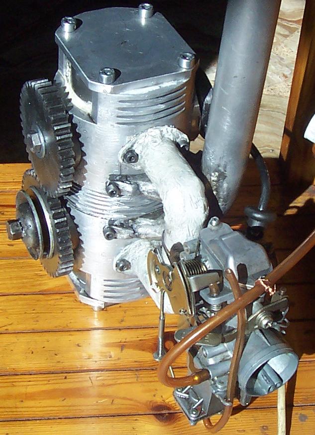
Speedman: "What is the liter capacity (PS/L / HP/L) of this tilting valve engine?


The specific power of the OPRE tilting is not known, yet.

Theoretically speaking, it has all the characteristics for top specific power (bhp/lit).

The state of the art two strokes (snowmobiles etc) have a peak specific torque of about 200mNt/lit (20mKp/lit).

Lets make a simple calculation:

With only 150mNt/lit (15mKp/lit) of torque for the OPRE tilting engine (i.e. with only 75% of the existing 2-strokes peak specific torque), the OPRE will provide:

15*1.4*6= 126bhp/lit at 6,000rpm (i.e. 42bhp from 333cc)

15*1.4*10= 210bhp/lti at 10,000rpm (i.e. 70bhp from 333cc)

15*1.4*15= 315bhp/lit at 15,000rpm (i.e. 105bhp from 333cc)

At 6,000rpm the speed at the edges of the 1m diameter propellers of the OPRE tilting Flyer is about 10% lower than the sound velocity; and the mean piston speed of the pistons is only 6m/sec, wherein the reliability is maximized. In the giant low-speed marine two-strokes, the 6m/sec mean piston speed is where the time between overhauls maximizes.

At 15,000rpm (which seems an extreme speed) the mean piston speed of the OPRE tilting 84x(30+30) is only 15m/sec (for comparison, the mean piston speed in a car engine having 90mm piston stroke and revving at 6,000 rpm is 18m/sec).


On the other hand, for several applications (like a flyer or a paraglider or a small airplane or helicopter) more important than the power to capacity ratio (specific power) is the power to weight ratio (bhp/Kp) wherein the OPRE tilting is even better.
The perfect balancing (vibration free) of the OPRE tilting is for free: it needs neither balancing shaft, not gearing. Compare it to the existing two or four stroke engines.


Thanks
Manolis Pattakos

#23 MatsNorway

MatsNorway
  • Member

  • 2,822 posts
  • Joined: December 09

Posted 01 November 2013 - 10:10

I guess a simple way to calculate power is to get a propeller and measure the trust and rpm. Given that the efficiency of the propeller is known and such. I take it is more engineering to make a dyno. The easiest but not cheap i guess would be to rent a dyno shop for testing.


btw. Manolis The DXF is converted to a Inventor file, It worked fine.


Edited by MatsNorway, 01 November 2013 - 10:10.


#24 manolis

manolis
  • Member

  • 935 posts
  • Joined: May 03

Posted 01 November 2013 - 19:12

I guess a simple way to calculate power is to get a propeller and measure the trust and rpm. Given that the efficiency of the propeller is known and such. I take it is more engineering to make a dyno. The easiest but not cheap i guess would be to rent a dyno shop for testing.

btw. Manolis The DXF is converted to a Inventor file, It worked fine.

Mats,

thanks for the files.


Regarding the calculations for the power of the OPRE tilting in my previous post:

The torque is always a good start.

The torque has to do with the volumetric efficiency, with the efficiency of the combustion and with the mechanical efficiency of the engine.

The torque is proportional to the energy provided by the engine per crankshaft rotation.

In most modern four-stroke non-supercharged engines a specific torque of nearly 10mKp/lt (or 100mNt/lit) is the case. A little more for the high revving engines (for instance, the R1200GS BMW boxer of 2013 has 10.9 mKp/lit), a little less for family car engines.

This means that for every liter of capacity and for every rotation of the crankshaft of a modern 4-stroke engine, the engine provides some 100Nt * 1m * 2 * pi = 628 Joules.

If the crankshaft rotates with 100 rounds per second (i.e. the engine is revving at 6000 rpm) the power provided per liter of engine capacity is 628 Joules *100 c /sec = 63 Kw (or 86 bhp).

In the two-stroke engines the number of combustions per crankshaft rotation doubles.
In a first approach the two-stroke is expected to provide double specific torque (mKp/lit) and double specific power (bhp/lit).
For instance, the 6000-Series Arctic Cat 600 C-TEC2 from 599cc provides 123bhp at 8100 rpm, which gives a specific torque of 18mKp/lit.

The 15mKp/lit for a free breathing two-stroke is a reasonable / pessimistic assumption.
Having the specific torque, the rpm define the specific power output.


A low budget prototype has neither the right materials (for instance: the pistons of the OPRE tilting are from hard aluminum, 7000 series, not because it is the proper material, but because it is available), nor the necessary construction accuracy, nor the correct surface treatment, nor the correct fuel system, nor the correct ignition system, nor ...
I.e. the measurement of the power or torque output of a low budget prototype is meaningless.


For the measurement of the power, the thrust force of a propeller is not a good way, unless we are sure for the plots of the propeller as the propeller manufacturer gives them. Many prop makers avoid completely giving such plots. The others who give such plots, do not guarantee their precision. I.e. the problem of the correct power measurement is not really solved this way. Any errors in the characteristic curves of the propeller, pass to the power measurement.


A much better and precise way for the power measurement of an engine is by using a heavy flywheel, like:

img0.jpg

The rhythm the flywheel accelerates gives the torque and power provided by the engine. This is the principle used in the inertia dynos.


Another way is by measuring the torque by a brake and a scale. It gives in real time (without other calculations) the torque provided by the engine. All it takes is a controllable brake acting on the flywheel, a beam and a weight movable along the beam (or a scale). It seems primitive, yet it is a simple and correct and direct method.

Thanks
Manolis Pattakos

#25 manolis

manolis
  • Member

  • 935 posts
  • Joined: May 03

Posted 16 November 2013 - 05:26

. . .
In most modern four-stroke non-supercharged engines a specific torque of nearly 10mKp/lt (or 100mNt/lit) is the case. A little more for the high revving engines (for instance, the R1200GS BMW boxer of 2013 has 10.9 mKp/lit), a little less for family car engines.
. . .

Why 10mKp/lt ?

And why the naturally aspirating (non-supercharged) gasoline engines cannot go way above the 10mKp/lit specific torque?

Per liter of capacity and per crankshaft rotation the four-stroke "handles" / "burns" (when it operates at full load, i.e. with wide open throttle) half a liter of air: as four-stroke it needs two crank rotation for a complete “cycle of operation”.

The mass of one liter of air is about 1.3gr (the air density at see level is 1.29 Kg/m^3) at normal conditions of pressure and temperature. I.e. per liter of four-stroke capacity, the mass of the air burned by the engine is 1.3gr/2=0.65gr.

The stoichiometric mixture has 14.7 parts of air mass and one part of fuel mass.
This means that per liter of capacity and per crankshaft rotation a four-stroke burns 0.65/14.7=0.044gr of fuel.

The thermal energy of 1 Kg of gasoline is about 43.000KJ.
This means that per lit of capacity of a four-stroke, in one crankshaft rotation the energy of the fuel “burned” is 0.044gr*43.000KJ/Kg=1892 Joule.

Operating at a 33% brake thermal efficiency (the engine of Prius of Toyota has a peak break thermal efficiency of 38%, the peak break thermal efficiency of the giant marine Diesels is above 50%), per crankshaft rotation and per liter of capacity the four stroke provides: 1892*0.33=624J

At 6000rpm this gives a power output of 62.4kW (or 85bhp), with the respective specific torque calculated at 85 / ( 1.4 * 6 ) = 10.2 mKp.

According the wikipedia, in 2006 Toyota F1 announced an approximate 740 hp (552 kW) output at 19000 rpm for its new RVX-06 engine.
At 19.000rpm this 2,398cc F1 engine provides a torque of 740 / (1.4 * 19 ) = 27.8 mKp , i.e. it has a specific torque of 11.6 mKp / lt, which is only 6.5% higher than the specific torque of the BMW boxer of 2013.
Reasonably the brake thermal efficiency of a high revving F1 engine is not expected to be high (shape of combustion chamber, friction etc).
Reasonably the substantially increased volumetric efficiency is the cause of the increased specific torque.
The valve train together with the intake and exhaust systems exploit the inertia of the air at high revs and achieve to trap inside the cylinder substantially more air than the capacity of the cylinder.
The drawback is the bad operation at medium - low revs and partial loads.


With the Variable Valve Actuation systems (VVA systems) a good volumetric efficiency can be maintained in a wide range of revs as shows the plot
no70Analysis.gif
at http://www.pattakon....takonRoller.htm wherein the blue curve is the lambda times the injection duration, i.e. it is the quantity, per cycle, of air that is handled by the engine.
A continuously variable VVA system is behind the above flat "volumetric" efficiency, as shows the following plot:
ValveLifts.gif
at http://www.pattakon....attakonVtec.htm


In the two-stroke engines things are not too different.

Thanks
Manolis Pattakos