Jump to content


Photo

new piston ring design


  • Please log in to reply
273 replies to this topic

#1 unclematt

unclematt
  • Member

  • 146 posts
  • Joined: February 11

Posted 05 March 2011 - 15:24

The glitch last night deleted the thread topic, so reposting:

Federal Mogul recently revealed a new oil ring design that they say reduces friction 15% and cuts oil consumption in half. The new rings were designed especially for use in high compression or direct injection engines. Check it out here

Posted Image

If anyone using this new ring design, please post your experiences.

I also found a page about Nissans 1.2 liter engine, that claims a 30% reduction in engine friction utilizing diamond-like-carbon coatings on valvetrain components and piston rings here

I have always been a fan of DLC coatings for friction reduction, and have been amazed at the slow pace at which they have been utilized/adopted in the automotive industry.

Anyone have any other new ring designs or advancements to post that reduce friction?

Edited by unclematt, 05 March 2011 - 15:26.


Advertisement

#2 gruntguru

gruntguru
  • Member

  • 7,706 posts
  • Joined: January 09

Posted 06 March 2011 - 04:20

It certainly makes sense that the "leading" and "trailing" ramps to the contact are should be different shapes. It also makes sense that the shape of the leading edge should change as the ring wears - it looks like some R&D has gone into that fancy profile. Having said all that - where's the rocket science?

#3 Grumbles

Grumbles
  • Member

  • 326 posts
  • Joined: September 09

Posted 06 March 2011 - 05:55

A couple of questions: have the OEMs reverted to one piece oil rings? Most of what I play with still uses 3 piece assemblies. It makes sense that a smaller, harder contact area with less ring tension would reduce friction while still controlling the oil. But if the contact face has a DLC or similar how does it conform or wear in to the wall? Or does it rely on the flexibility of the ring itself to allow conformance?

#4 Magoo

Magoo
  • Member

  • 3,856 posts
  • Joined: October 10

Posted 06 March 2011 - 11:15

One-piece oil ring is a diesel thing. Or two-piece in many instances -- same basic config with a backing coil spring for tension. Check the two pages below or page through the whole manual, it's not bad.

http://www.federalmo.../section_21.htm

http://www.federalmo.../section_23.htm


#5 unclematt

unclematt
  • Member

  • 146 posts
  • Joined: February 11

Posted 06 March 2011 - 13:27

It certainly makes sense that the "leading" and "trailing" ramps to the contact are should be different shapes. It also makes sense that the shape of the leading edge should change as the ring wears - it looks like some R&D has gone into that fancy profile. Having said all that - where's the rocket science?

FM doesn't say what the "coating" is in their marketing material, so maybe that is where the "rocket science" comes in. Maybe DLC?

#6 cheapracer

cheapracer
  • Member

  • 10,388 posts
  • Joined: May 07

Posted 06 March 2011 - 15:15

One-piece oil ring is a diesel thing.


Actually I spent all my early years pulling apart Honda motorcycles and they were all one piece back in the 70's (all the other general brands were 2 strokes).


#7 Magoo

Magoo
  • Member

  • 3,856 posts
  • Joined: October 10

Posted 06 March 2011 - 16:47

Actually I spent all my early years pulling apart Honda motorcycles and they were all one piece back in the 70's (all the other general brands were 2 strokes).


I remember those... and remember thinking how un-Japanese it was. Why use one part when three will do the same job.


#8 cheapracer

cheapracer
  • Member

  • 10,388 posts
  • Joined: May 07

Posted 06 March 2011 - 18:03

I remember those... and remember thinking how un-Japanese it was. Why use one part when three will do the same job.


:lol: That will go over the top of many!


#9 gruntguru

gruntguru
  • Member

  • 7,706 posts
  • Joined: January 09

Posted 06 March 2011 - 23:00

FM doesn't say what the "coating" is in their marketing material, so maybe that is where the "rocket science" comes in. Maybe DLC?

The drawing doesn't show the coating to be different to the "Standard Oil Ring"
.

#10 unclematt

unclematt
  • Member

  • 146 posts
  • Joined: February 11

Posted 07 March 2011 - 00:48

Does anyone know, or have a guess, as to how this new ring design would react to being run across cylinder wall ports? Better or worse than the typical 3-piece design?

Someone mentioned Honda 2 stroke oil rings were 1 piece in the seventies, how did those hold up to exposure to that kind of service?

Edited by unclematt, 07 March 2011 - 00:50.


#11 desmo

desmo
  • Tech Forum Host

  • 32,138 posts
  • Joined: January 00

Posted 07 March 2011 - 03:00

I remember those... and remember thinking how un-Japanese it was. Why use one part when three will do the same job.

:up: :lol:


#12 malbear

malbear
  • Member

  • 309 posts
  • Joined: September 02

Posted 07 March 2011 - 06:58

Does anyone know, or have a guess, as to how this new ring design would react to being run across cylinder wall ports? Better or worse than the typical 3-piece design?

Someone mentioned Honda 2 stroke oil rings were 1 piece in the seventies, how did those hold up to exposure to that kind of service?

The hondas were 4 stroke as I recall
my prototype 3 was bassed on a honda 125
cheers
malbeare

http://www.sixstroke.com/gallery.htm

Edited by malbear, 07 March 2011 - 07:02.


#13 cheapracer

cheapracer
  • Member

  • 10,388 posts
  • Joined: May 07

Posted 07 March 2011 - 08:07

Someone mentioned Honda 2 stroke oil rings were 1 piece in the seventies, how did those hold up to exposure to that kind of service?


The Honda 2 stroke oil rings lasted very poorly back then, every time I stripped one down I found they had disintegrated.

#14 malbear

malbear
  • Member

  • 309 posts
  • Joined: September 02

Posted 07 March 2011 - 08:36

The Honda 2 stroke oil rings lasted very poorly back then, every time I stripped one down I found they had disintegrated.

2 strokes dont have oil control rings only compression rings as the oil system is total loss as suplied via premix petrol or oil injection to the carb as in the old yamaha system or to the roller bearings and piston as in the suzuki system.
malbeare

#15 unclematt

unclematt
  • Member

  • 146 posts
  • Joined: February 11

Posted 07 March 2011 - 08:58

2 strokes dont have oil control rings only compression rings as the oil system is total loss as suplied via premix petrol or oil injection to the carb as in the old yamaha system or to the roller bearings and piston as in the suzuki system.
malbeare

OOOps. you are quite right, I forgot about that part of 2-stroke design that existed back then. I guess I am curious if this new ring design could be used in the OPOC engine, or other 2-stroke designs that have ported cylinders.

#16 cheapracer

cheapracer
  • Member

  • 10,388 posts
  • Joined: May 07

Posted 07 March 2011 - 11:58

2 strokes dont have oil control rings
malbeare


I guess thats why they had disintegrated, nudge, nudge, wink, wink! (I didn't expect you to bite :lol:;) )


OOOps. you are quite right, I forgot about that part of 2-stroke design that existed back then. I guess I am curious if this new ring design could be used in the OPOC engine, or other 2-stroke designs that have ported cylinders.


Any typical common small engine (motorbikes, lawn mowers etc) series 2 stroke engine is oil ring free and always has been throughout history to this very day but I never played with big diesels or opposed piston engines enough to comment on them.

Yes but they may need to be pinned and because they won't be able rotate in the bore that will decrease life. If free to rotate then end snagging is a real issue and must be overcome.

Edited by cheapracer, 07 March 2011 - 12:06.


#17 malbear

malbear
  • Member

  • 309 posts
  • Joined: September 02

Posted 07 March 2011 - 18:14

I guess thats why they had disintegrated, nudge, nudge, wink, wink! (I didn't expect you to bite :lol:;) )


Any typical common small engine (motorbikes, lawn mowers etc) series 2 stroke engine is oil ring free and always has been throughout history to this very day but I never played with big diesels or opposed piston engines enough to comment on them.

Yes but they may need to be pinned and because they won't be able rotate in the bore that will decrease life. If free to rotate then end snagging is a real issue and must be overcome.

I thought thay you were f
just givimg me an In
GM twostrokes

http://www.ss346.com...8_V16Piston.jpggm twostroke pistonPosted Image
the small ports at the bottom of the sleve were numerous so that the compression rings on the top of the piston did not need pegs as the ports were not wide enough fo a ring to stick into and jam.
the oil scrapers never entered or traversed these ports
malbeare Visit My Website
Posted Image

Edited by malbear, 07 March 2011 - 18:17.


#18 unclematt

unclematt
  • Member

  • 146 posts
  • Joined: February 11

Posted 07 March 2011 - 19:54

Double oops, I have read that info many times in the past, and don't know what I was thinking. I guess posting when you have the death flu maybe isn't such a good idea.

#19 unclematt

unclematt
  • Member

  • 146 posts
  • Joined: February 11

Posted 07 March 2011 - 19:57

Let me ask you guys this, sick as I am: is it possible to design an oil control ring that is capable of passing over small cylinder ports without negative consequence? Would this new 1 piece FM ring design handle that without issue?

Advertisement

#20 cheapracer

cheapracer
  • Member

  • 10,388 posts
  • Joined: May 07

Posted 07 March 2011 - 21:14

Let me ask you guys this, sick as I am: is it possible to design an oil control ring that is capable of passing over small cylinder ports without negative consequence? Would this new 1 piece FM ring design handle that without issue?


No and doesn't matter if 1, 2 or 3 piece ring. What is not commonly written past "the oil ring scrapes oil of the cylinder wall" is that the oil is then transfered to the sump via the holes in the piston by pressure differences between the cylinder wall and the crankcase. The common second compression ring is also an "oil scraper" that more or less gathers the oil for the oil control rings (note the proper name) to do their work. Diesels often have 3 rings compression rings to control that pressure differential to allow more oil onto the walls not to "seal the compression better" as often stated - note when pulling a stuffed diesel down how dry and scuffed/scored the cylinder is?

By crossing over ports you are going to upset the crankcase pressure. Study up on PCV systems and the effects of dry sump scavenge systems and what effect they have on oil control.

The whole science of rings is quite interesting and generally one of the worst reported as to their workings to the layman.

Edited by cheapracer, 07 March 2011 - 21:16.


#21 venator

venator
  • Member

  • 58 posts
  • Joined: June 08

Posted 07 March 2011 - 21:20

Let me ask you guys this, sick as I am: is it possible to design an oil control ring that is capable of passing over small cylinder ports without negative consequence? Would this new 1 piece FM ring design handle that without issue?

Two-stroke engines with separate charging pistons, such as those of the DKW Schwebeklasse (1930s) and the Trojan light commercial (1950s), i.e. non-crankcase-compression two-stroke engines, used such rings, as their crankcase contained lubricating oil. As for durability of those designs, I would not know, it was before my time.

Edited by venator, 07 March 2011 - 21:21.


#22 unclematt

unclematt
  • Member

  • 146 posts
  • Joined: February 11

Posted 08 March 2011 - 00:22

No and doesn't matter if 1, 2 or 3 piece ring. What is not commonly written past "the oil ring scrapes oil of the cylinder wall" is that the oil is then transfered to the sump via the holes in the piston by pressure differences between the cylinder wall and the crankcase. The common second compression ring is also an "oil scraper" that more or less gathers the oil for the oil control rings (note the proper name) to do their work. Diesels often have 3 rings compression rings to control that pressure differential to allow more oil onto the walls not to "seal the compression better" as often stated - note when pulling a stuffed diesel down how dry and scuffed/scored the cylinder is?

By crossing over ports you are going to upset the crankcase pressure. Study up on PCV systems and the effects of dry sump scavenge systems and what effect they have on oil control.

The whole science of rings is quite interesting and generally one of the worst reported as to their workings to the layman.

Assume for a moment that the differential pressure issue isn't a problem due to design parameters. Would any kind of oil control ring (1,2, or 3) be able to cross over ports without damage or durability issues IYO?

#23 cheapracer

cheapracer
  • Member

  • 10,388 posts
  • Joined: May 07

Posted 08 March 2011 - 03:02

Assume for a moment that the differential pressure issue isn't a problem due to design parameters. Would any kind of oil control ring (1,2, or 3) be able to cross over ports without damage or durability issues IYO?


Of course when you look at Malbears examples above with the small multiple ports I note on those pistons the oil control ring is almost at the very bottom of the skirt obviously to avoid going over the ports but for the pressure differentuial reason I mentioned while in the meantime the compression rings are most obviously going across.

Thats only guessing by the way, as I said my 'hands on' with big 2 stroke diesels is very limited and I stand to be corrected.

#24 Grumbles

Grumbles
  • Member

  • 326 posts
  • Joined: September 09

Posted 08 March 2011 - 09:51

All the Detroit 2 strokes I've worked on have the oil ring (one piece with expander) on the bottom of the skirt so that it doesn't pass over the inlet ports. And seeing as the exhaust valves are already open by the time the compression rings uncover the ports the pressure differential conditions over the rings would be basically the same as in a conventional 4 stroke. Some oil does make its way into the ports, so it and the condensation that collects in the air chest is continually drained off - onto the road - by "slobber tubes".

I'd imagine one piece oil rings would be able to pass over a symmetrical port pattern (eg. DD) but you'd still need a ring below the ports to limit the amount of oil smeared into the port windows by the piston skirt.


#25 Magoo

Magoo
  • Member

  • 3,856 posts
  • Joined: October 10

Posted 08 March 2011 - 16:23

I thought thay you were f
just givimg me an In
GM twostrokes

http://www.ss346.com...8_V16Piston.jpggm twostroke pistonPosted Image
the small ports at the bottom of the sleve were numerous so that the compression rings on the top of the piston did not need pegs as the ports were not wide enough fo a ring to stick into and jam.
the oil scrapers never entered or traversed these ports
malbeare Visit My Website
Posted Image


Hey, those are 248A or 278A sleeves. Cleveland Diesel (as opposed to Detroit Diesel) badged GM Diesel but the same thing, essentially. Bigger. Doing a tuneup on your WWII submarine?


#26 Paul Vanderheijden

Paul Vanderheijden
  • Member

  • 65 posts
  • Joined: December 07

Posted 09 March 2011 - 02:02

In recent times I have been playing around with several treatments for ring/cylinder control.

1. Treating the cast iron cylinder bores with a Plasma deposited surface using the Sumabore process. This puts down a very tough (yet porous) layer that retains oil. It is "plateau honed" and then polished for an almost mirror-like surface.
2. The rings themselves are DLC coated (using Bakaert-Sorevi processes) after being isotropically polished and lapped to the "test bore" of the appropriate diameter, using 8 micron diamond paste. This includes the top/bottom rails of the 3-piece oil control ring. Ring pack is .8mm top ring, 1mm second ring and 2.5mm 3-piece oil control ring.
3. Piston skirts are hand-polished and then DLC coated using Bakaert-Sorevi Cavidur-B , multi-layer process, suitable for aluminium substrates. This provides the skirt with a very hrad, slippery surface.
4. Top compression ring groove is radial gas ported.

The end result is a cylinder wall that hold just the right amount of oil to promote a semi-hydrodynamic wedge effect (similar to a bearing surface) for both the rings and the pistons skirts. The only time that the piston skirt may come into contact with the cylinder wall is at the reversal points of travel.

This results in very good cylinder sealing and quite minimal wear characteristics. Leakdown hold in excess of 98% is not uncommon on a warm motor. Under running conditions there is virtually no leakage at all.

The "new" oil control ring design illustrated at the beginning of this thread would probably work OK, particularly if DLC coated/lapped edges were adopted. However a great deal will depend on the care with which the rings and the mated surfaces are prepared. Perhaps for production installations it might be OK, but for all out racing situations, I am not sure that there is much "new" about it.

Cheers


#27 unclematt

unclematt
  • Member

  • 146 posts
  • Joined: February 11

Posted 11 March 2011 - 04:03

So with regard to these 2 stroke pistons and cylinders, I have a question for diesel applications:

Which compression ring moves into the lubrication overlap zone under the lower cylinder ports? Or do both compression rings need to move into that zone? How much overlap needs to occur at a minimum between the oil ring and compression ring(s) to achieve sufficient oil being carried up the cylinder walls? Anyone know how much overlap there is in the OPOC motor for example?


#28 cheapracer

cheapracer
  • Member

  • 10,388 posts
  • Joined: May 07

Posted 11 March 2011 - 04:31

Anyone know how much overlap there is in the OPOC motor for example?


Click on the "Investor" link, throw in another million and I'm sure they will share the info over a 3 year period.

Maybe Man knows some of your answers, try PM'ing him or emailing from the Pattakon website - you can also compare the OPOC engine with his OPRE and PatOP engines that he seems to build and get running in a couple of months on a few hundred dollars in comparison to OPOC's mega $millions and 8 years.

http://www.pattakon.com/

Well I just did something scientific, I went to their website and watched the 3D animation which you would think would be reasonably accurate and the oil rings cover the entire compression rings area and then some. So the OPOC engine still has combustion troubles (self admitted), so why didn't they tackle that area first on some commecially available engines instead of taking peoples millions of investment to build a different engine that was always going to have an identical combustion chamber? I note Wilfred Von Rippyouoff is on the board of Transonic Combustion no doubt hoping to further his funds through the "supercritical" injector that will be the godsend for his OPOC. Of course this will take some years to test and develop - oh and did I mention investment potential?


#29 malbear

malbear
  • Member

  • 309 posts
  • Joined: September 02

Posted 11 March 2011 - 10:58

Click on the "Investor" link, throw in another million and I'm sure they will share the info over a 3 year period.

Maybe Man knows some of your answers, try PM'ing him or emailing from the Pattakon website - you can also compare the OPOC engine with his OPRE and PatOP engines that he seems to build and get running in a couple of months on a few hundred dollars in comparison to OPOC's mega $millions and 8 years.

http://www.pattakon.com/

Well I just did something scientific, I went to their website and watched the 3D animation which you would think would be reasonably accurate and the oil rings cover the entire compression rings area and then some. So the OPOC engine still has combustion troubles (self admitted), so why didn't they tackle that area first on some commecially available engines instead of taking peoples millions of investment to build a different engine that was always going to have an identical combustion chamber? I note Wilfred Von Rippyouoff is on the board of Transonic Combustion no doubt hoping to further his funds through the "supercritical" injector that will be the godsend for his OPOC. Of course this will take some years to test and develop - oh and did I mention investment potential?

quite frankly I admire Pattakons work. I have built and paid for my own prototypes , Unfortunatly I suffered a setback for many years culminating in an australian federal court case .
I invite anyone to read the judgement as it is a publicly available document, and form your own oppinion.
I will be constructing and testing my own prototypes with the aid of my friend Steve.
Visit My Website
Please dont bother me trying to invest just let me know if you have an aplication after I publish results

#30 cheapracer

cheapracer
  • Member

  • 10,388 posts
  • Joined: May 07

Posted 11 March 2011 - 11:49

Quite frankly I admire Pattakons work. I have built and paid for my own prototypes ,


Indeed, Man, Yourself and Felix are legends in my book :up:

#31 unclematt

unclematt
  • Member

  • 146 posts
  • Joined: February 11

Posted 11 March 2011 - 13:32

I too appreciate all the individual engine designers/builders out there! I just laugh at all their detractors, who sit around and arm chair quarterback, while doing zero innovation or designing/building of their own. I too am working on an engine design, and have been met with huge resistance from people who simply don't want to consider anything new, and are firmly entrenched in the status quo and "invented here".

I recently had such an experience at a certain engineering tips forum (which shall remain nameless), and manolis had the same un-welcome treatment there, and was eventually banned, just like I was. Not because we were posting inappropriate things, but because our topics were getting a great deal of views, responses, and interest, and the mods didn't like that. You can post all the verifiable information you want to these people, and they will just sit there with arms crossed, forehead furrowed, and shaking their head and wagging their finger at anything outside their wittle box. Most admitted to me they wouldn't even read the papers I posted to back up my theories or suggestions, they simply dismissed them out of hand. Makes you wonder how they ever got anywhere as engineers at all.

My favorite was when one of the main moderators informed me that trying to utilize "direct injection" would doom my whole project to failure because it was on the "bleeding, cutting edge". When I pointed out to him that many direct injection common rail systems were available commercially TODAY, I was immediately banned! lol


#32 unclematt

unclematt
  • Member

  • 146 posts
  • Joined: February 11

Posted 11 March 2011 - 14:02

Well I just did something scientific, I went to their website and watched the 3D animation which you would think would be reasonably accurate and the oil rings cover the entire compression rings area and then some. So the OPOC engine still has combustion troubles (self admitted), so why didn't they tackle that area first on some commecially available engines instead of taking peoples millions of investment to build a different engine that was always going to have an identical combustion chamber? I note Wilfred Von Rippyouoff is on the board of Transonic Combustion no doubt hoping to further his funds through the "supercritical" injector that will be the godsend for his OPOC. Of course this will take some years to test and develop - oh and did I mention investment potential?

Not sure why you say they are having "combustion troubles" with the OPOC engine because they have complete overlap between oil and compression rings...

I have also heard a lot of encouraging news coming from transonic, and hope their supercritical injection is viable and produces the results they claim.

Yes, there are many people out there who use patents, websites, and questionable engineering to relieve people of their money. But not all innovators are like that, are they? People that come up with new ideas should definitely be met with healthy levels of scepticism, and held to rigorous level of confirmation, but too many mental people wait on internet forums licking their chops just waiting for new ideas to ridicule or shoot down without basis. Those kind of people get their jollies from tearing down ideas instead of making valid points backed up by verifiable sources.

Its almost as if since THEY couldn't come up with anything new and viable in their career or lifetime, that they assume no one else can either...

Edited by unclematt, 11 March 2011 - 14:03.


#33 malbear

malbear
  • Member

  • 309 posts
  • Joined: September 02

Posted 11 March 2011 - 20:09

[quote name='unclematt' date='Mar 11 2011, 14:02' post='4889160']
Yes, there are many people out there who use patents, websites, and questionable engineering to relieve people of their money. But not all innovators are like that, are they? People that come up with new ideas should definitely be met with healthy levels of scepticism, and held to rigorous level of confirmation, but too many mental people wait on internet forums licking their chops just waiting for new ideas to ridicule or shoot down without basis. Those kind of people get their jollies from tearing down ideas instead of making valid points backed up by verifiable sources. ]


One former, one current ... Date Added: 16/11/2010
Matiuk & Jack


Reg P from Western Australia emailed us regarding Sir Jack - yes Reg, he was a director of the company between 2005 and 2007. Shown below is a photograph taken last month of Sir Jack with our newly appointed director Edwin Matiuk.


JBEC directors

I name and expose the new JBEC P/L company, and publish that the same old JBE Board cohort directors are now moving sideways to do more of the same (as they did with Pulse Fuel and JBE) as Directors of the new JBEC P/L board, which includes Edwin Matiuk, Alan Casey, Gail Casey, Tony Hall.
Judge Jagot determined that Alan Casey (Director of JBE P/L and now JBEC P/L) engaged in misleading & deceptive conduct, that Alan Casey (according to Judge Jagot) deposited moneys subscribed to company for (”patent commercializing intended”) technology development into his own personal bank account, That Alan Casey (according to Judge Jagot) used company (“development”) funds for his own personal daily needs, that the values applied to the company patents by Alan Casey proved exaggerated and inflated.

Mr. Edwin Matiuk appears to now be leading the JBEC P/L charge as leader and CEO of yet another (latest) incarnation of a “Patent Commercialisation” company, who’s directors “coincidently” are Alan Casey, Gail Casey, Anthony Hall, the very same people whom were involved in the previous two company failures, the very same Alan Casey whom appear to have thus far squandered in excess of 1,5 million dollars of subscribers moneys, during the time Alan Casey was in control of Pulse Fuel Technologies, later name change in 2004 to Jack Brabham Engines P/L. the same Alan Casey and Gail Casey, who together with Sir Jack Brabham and Jack Brabham Engines P/L failed in their collective 2007 filed proceedings against me in Federal Court of Australia Sydney, and were in turn singly and severally ordered by Judge Jagot late 2010 to pay the sizable Malcolm Beare/Respondents court case costs which they have yet to pay. The same Alan Casey and Gail Casey who now appear to be slithering sideways towards setting up another company intended to reportedly do more of the same under the latest guise of JBEC P/L. Alan Casey, Gail Casey, and Anthony Hall have evidently now enlisted the expert help of Edwin Matiuk.

Edited by malbear, 11 March 2011 - 20:21.


#34 unclematt

unclematt
  • Member

  • 146 posts
  • Joined: February 11

Posted 12 March 2011 - 01:43

Anyway, back on the original topic: NEW PISTON RING DESIGN

I finally found what the guys at OPOC/EcoMotors are using to solve lubrication/exhaust port issues. They use a special "scraper ring" that sits just below the compression ring pack. This scraper ring has a groove that scoops up oil from below the exhaust ports in the ring overlap area. Oil is moved into the ring's interior groove, away from the cylinder wall/exhaust ports. Then when the piston hits TDC, momentum slings the oil out of the groove and onto the cylinder walls. This is supposed to provide oiling at the top of the cylinder, which is the hardest part of the stroke to lubricate in uniflow 2-strokes where the oil control ring never passes the exhaust ports.

You can read all about it and check out diagrams HERE

US20100326394A1 patent application

If this idea is working for them, I must say I admire the simple solution they came up with to solve a thorny problem. They seem to be doing good things over there at EcoMotors.

Edited by unclematt, 12 March 2011 - 04:07.


#35 manolis

manolis
  • Member

  • 938 posts
  • Joined: May 03

Posted 25 March 2011 - 15:41

I saw your thread only yesterday.
But better late than never.

The cylinder liner of the PatOP prototype ( http://www.pattakon....ttakonPatOP.htm ) is from a Perkins Diesel engine (3 ¼’ external diameter, 3 1/8’ internal diameter). The original 79.375mm internal diameter of the Perkins liner is increased to 79.5mm to fit with the standard piston rings for the VW Tdi diesel engine (aftermarket, npr).

From the 12 piston rings of the piston-ring-set, only the four top compressor rings (chromium with barrel cut-view) are used, two on each piston of the PatOP prototype; their shape has nothing to do with a scraper ring shape; the top ring has no direction, i.e. it displaces the oil it finds equally at both directions.

The scraper rings of the set (not used in the PatOP prototype) have a substantially trapezoidal cut-view and specific direction: the bigger diameter goes down.

In the four stroke Tdi engine the cylinder wall needs oil: without an oil film between the piston skirt and the cylinder wall, the thrust forces will soon destroy the piston.
The piston skirt floats on the oil, pretty much the way a boat floats on the water (need for a thick oil film)
More correctly the piston skirt slides on the oil film, like a skier on the see water.
The thrust forces create the torque.
The instant torque equals to the thrust force times its eccentricity from the crankshaft axis.

The scraper ring (i.e. the second compression ring) sweeps the oil downwards, towards the crankcase (its shape allows the oil to pass downwards and prevents it from going upwards at the combustion chamber direction).
The material and the surface finishing of the liner are such that a tiny quantity of oil – like a dye – remains “glued” on the cylinder wall, no matter how efficiently the scraper ring works.

The top ring – which is of barrel cut view – finds the “lubricant –dye” on the cylinder wall and slides over it. At TDC and BDC, according Taylor, there is metallic contact for a few degrees, but the small speed of the piston near TDC and BDC helps for reduced wear of the liner and of the compression rings, at these stroke-ends.


In the crosshead engines (like the giant Sulzer marine engines) the piston skirt does not thrust on the cylinder wall, the piston does not “float” on a thick oil film: it does not touch any film or any liner.
A tiny quantity of oil – like a dye – on the liner is adequate for the reliable operation of the compression rings (case similar to the compression rings of the four stroke Tdi mentioned above).


With the crosshead architecture (to avoid the thrust loads on the cylinder liner) and an immovable scrapper ring below the ports (this ring sweeps the oil from the piston skirt towards the crankcase direction) a tiny quantity of lubricant on the cylinder liner – just like in the four stroke – protects the compression rings from metallic contact to the cylinder wall. This “lubricant dye” is quite difficult to escape to the ports. The lubricant consumption is comparable to that of the four stroke engines; from experience (and from many comments on the web) the reputable four-stroke Honda VTEC B16A2 engine consumes at high revs (say above 5, 6, 7, 8.000 rpm) more oil than a two stroke.

The crosshead architecture for the two stroke engines seems, from any viewpoint, way better as regards the lubricant consumption and emissions.

It would be great news for the crosshead pistons that the “ping pong” of the oil among the rings of the OPOC engine of EcoMotors (US20100326394A1 patent application) works in practice, because it takes time to find out how much oil is optimum to allow to pass the scrapers.

In case the oil “ping pong” in the OPOC pistons is not practical, EcoMotors can consider using the architecture of the PatPOC crosshead (below) in their engines (the width of the engine is not increased).

And talking for the OPOC:

The Junkers-Doxford below

Posted Image

has a strong unbalanced 2nd order inertia force.

The OPOC engine combines two Junkers-Doxford that share the same crankshaft.
Unless I miss something important, all the idea behind the OPOC is the vibration-free operation, or more precisely the almost-vibration-free operation.
Almost because the offset between the two opposed cylinder axes inevitably causes an unbalanced 2nd order inertia rocking couple (with the balance program, at pattakon Teaching, it is easy to make, at the special arrangements, the balancing analysis of the OPOC)
The reciprocating mass of the inner pistons (those with the short connecting rods) of the OPOC must be equal to the reciprocating mass of the outer pistons (those with the double long connecting rods and the long wrist pins). Reciprocating mass is the mass of the piston, of the piston rings, of the piston wrist pin and of the upper part (about 1/3) of the connecting rod(s) of the piston. I.e. mass must be added to the inner pistons, otherwise the OPOC is not well balanced.


In comparison, here is the PatPOC engine:

Posted Image

It looks like as half an OPOC, or as a complete Junkers-Doxford, yet it is different. The green frame reciprocates linearly. The connecting rods are all push-rods.

For more details: http://www.pattakon....takonPatPOC.htm wherein, among others, a different approach for variable capacity engines is shown.

The vibration-free quality of the single-cylinder PatPOC is comparable to that of the OPOC two-cylinder basic-module. Which of the two is better depends on the asymmetry of the ports timing: for symmetrical timing or for small asymmetry, the single cylinder PatPOC is slightly better than the two cylinder OPOC; for bigger asymmetry the OPOC is slightly better.

Here is the crosshead-PatPOC:

Posted Image

Both pistons are rid of thrust loads.
The mechanism operates with and without the pistons.
The immovable white scraper rings sweep the lubricant from the piston surface.
The cross-head design does not add “height” to the engine.


And here is the PatOP, which is crosshead by nature:

Posted Image

The grey immovable rings at the ends of the combustion cylinder are the scraper rings.


Is the crosshead architecture the solution of the lubricant consumption problem of the two strokes?
Time will show.

Thanks
Manolis Pattakos

#36 unclematt

unclematt
  • Member

  • 146 posts
  • Joined: February 11

Posted 26 March 2011 - 14:10

Hey Manolis, I have written you in the past about your scraper rings. As near as I can tell, and correct me if I'm wrong, but it appears they spread the oil out over the surface of the piston skirt, not on the walls of the cylinder or on piston rings. Since as you pointed out, the skirt does not touch the liner, how does this provide lubrication to the rings/liner?

#37 24gerrard

24gerrard
  • Member

  • 2,008 posts
  • Joined: March 11

Posted 26 March 2011 - 15:53

I think the Commer TS3 supercharged opposed piston two stroke, in production in the 1960s was better than any of the engines shown.


#38 manolis

manolis
  • Member

  • 938 posts
  • Joined: May 03

Posted 26 March 2011 - 20:53

unclematt:

At the BDC (maximum volume of the combustion chamber) the piston skirt is out of the cylinder liner; its surface is lubricated and cooled by the oil mist.

As the piston enters into the cylinder liner, the scraper ring sweeps the oil from the piston skirt surface.

And as in the four stroke engines, a tiny quantity of oil per cycle passes the scraper ring towards the combustion chamber.

A part of this oil follows the motion of the piston. As the quantity of this oil increases progressively on the piston skirt surface, it cannot help proceeding to the lower compression ring (the acceleration-deceleration of the piston helps, as well as the action of the scraper ring).
The oil that reaches the lower compression ring moves to the cylinder wall (especially when the piston decelerates near the Combustion Dead Center).
At equilibrium, the quantity of oil added to the piston skirt surface per cycle, equals to the quantity of oil deposited onto the cylinder wall by the lower compression ring per cycle.
This way the top compression ring moves along a lubricated cylinder wall.

The rest part of the oil that passes the scraper ring concentrates progressively at the bottom of the cylinder liner, above the scraper ring.
At the BDC, the clearance between the bottom compression ring and the scraper ring is small.
When the bottom compression ring reaches this “oil reservoir” at the bottom of the cylinder liner, it takes a small quantity of oil and lubricates the cylinder wall (and then the top compression ring). This oil is deposited to the cylinder wall when the piston decelerates near the Combustion Dead Center. At equilibrium, the quantity of oil taken by the bottom compression ring per cycle equals to the quantity of oil added to the “oil reservoir” per cycle.

The scraper ring must be properly designed to allow no more than necessary lubricant oil to pass (just like in the four stroke).


24gerrard:

The animation of the Commer TS:

Posted Image

may help you specify what are the functions it can better accomplish.
The controllable windows exe animation for the Commer TS is at Commer TS

Thanks
Manolis Pattakos


#39 Grumbles

Grumbles
  • Member

  • 326 posts
  • Joined: September 09

Posted 26 March 2011 - 22:02

I think the Commer TS3 supercharged opposed piston two stroke, in production in the 1960s was better than any of the engines shown.


Why? It's much heavier and bulkier, and the block would have to be made quite heavy to handle the loads imposed on the rocker pivots.

Manolis' designs, eg. the PatPOC, are much more compact and the block could be made much lighter. There are no "spreading" forces from rocker arms and the loads on the crank are horizontally opposing so the mains would be very lightly loaded.

I like the sound the old TS3 makes but really they were pretty bulky for their capacity and output when compared to say a 53 series GM. Neither the Commer or the GM were really supercharged to any extent - the blower was just for scavenging.


Advertisement

#40 unclematt

unclematt
  • Member

  • 146 posts
  • Joined: February 11

Posted 26 March 2011 - 22:04

The scraper ring must be properly designed to allow no more than necessary lubricant oil to pass (just like in the four stroke).

Manolis, no need to post more animations of various engines, though I know you love doing so.

With regard to your scraper ring design, it would have to allow enough oil past itself to fill in the gap between liner and piston in order to be able to tranfer oil as you described in your last post. Otherwise the only time oil would move between the piston skirt and liner would be when they came into contact with each other, which you claim doesn't happen often in engines where the piston has no side forces acting upon it. I understand some oil slips by the scraper, flows along the piston skirt to the rings, and they spread it on the liner according to your description, but that seems a long route for the oil to take. I think I prefer the OPOC engine design, where oil is simply slung out of the scraper ring and onto the liner along the top of the cylinder.

Edited by unclematt, 26 March 2011 - 22:09.


#41 Grumbles

Grumbles
  • Member

  • 326 posts
  • Joined: September 09

Posted 26 March 2011 - 22:16

One of the challenges with any of these engines using piston controlled exhaust ports will be managing the temperature of the piston at the hot end. I'd imagine that at the very least you'd need to be spraying quite a lot of oil underneath it and possibly also a GM style two piece piston with a steel crown and aluminium skirt. And even with all this temps. might still be a problem in a boosted SI application.

#42 24gerrard

24gerrard
  • Member

  • 2,008 posts
  • Joined: March 11

Posted 26 March 2011 - 23:46

With no reciprocation behind the hot piston and the potential to have that end of the cylinder open, would it be possible to include a water jacket inside the piston crown and circulate the coolant through flixible pipes?
Alternatively a relatively high volume jet of oil can be directed under the piston crown. Without reciprocating components in the way and a very efficient static oil sealing ring working on the outside of the piston base, this would not introduce excess oil into the cylinder.
The side rod operating the hot piston could also be adjustable in length during operation, using a hydraulicly operated scroll similar to current F1 gearbox selection, to facilitate changes in CR and port timing.
Ideal engine to use an exhaust turbo generator to achieve very high efficiency in a hybrid powertrain.
Love to develop one.
Still like the Commer TS3 though, that was very fuel efficient and I think better balanced.

#43 unclematt

unclematt
  • Member

  • 146 posts
  • Joined: February 11

Posted 27 March 2011 - 01:24

One of the challenges with any of these engines using piston controlled exhaust ports will be managing the temperature of the piston at the hot end. I'd imagine that at the very least you'd need to be spraying quite a lot of oil underneath it and possibly also a GM style two piece piston with a steel crown and aluminium skirt. And even with all this temps. might still be a problem in a boosted SI application.

I agree completely. The engine design I am working on has oil flowing up the center of the connecting rod to the base of the piston bowl for cooling purposes.

#44 24gerrard

24gerrard
  • Member

  • 2,008 posts
  • Joined: March 11

Posted 27 March 2011 - 01:29

I agree completely. The engine design I am working on has oil flowing up the center of the connecting rod to the base of the piston bowl for cooling purposes.


We did this back in the 70s on a BDA engine but I was never convinced the oil got where we wanted it to go because of the forces on the rod.
It would be much easier today to actualy see it working.

#45 unclematt

unclematt
  • Member

  • 146 posts
  • Joined: February 11

Posted 27 March 2011 - 02:24

We did this back in the 70s on a BDA engine but I was never convinced the oil got where we wanted it to go because of the forces on the rod.
It would be much easier today to actualy see it working.

I know this will raise eyebrows, but my engine has no piston pins, the piston and rod are one piece. So getting the oil to underneath the bowl for cooling is simplified when compared to more common engine designs.

#46 24gerrard

24gerrard
  • Member

  • 2,008 posts
  • Joined: March 11

Posted 27 March 2011 - 07:07

I know this will raise eyebrows, but my engine has no piston pins, the piston and rod are one piece. So getting the oil to underneath the bowl for cooling is simplified when compared to more common engine designs.


Have you thought about water cooling the piston with a cast in jacket and flexible feed?
Using flexible pipes, or perhaps sliding tubes with sealing rings.

Patent?

Edited by 24gerrard, 27 March 2011 - 07:10.


#47 manolis

manolis
  • Member

  • 938 posts
  • Joined: May 03

Posted 27 March 2011 - 15:05

Unclematt:
“Manolis, no need to post more animations of various engines, though I know you love doing so.”

With an animated drawing (especially a controllable one, wherein you can accelerate the motion, you can reverse or suspend the motion, you can remove some parts to unhide the rest, and so on) in a couple of seconds you can say a whole detailed story to anybody on earth (no matter he speaks Chinese, or Greek, or English).
It is an international language.
With some good animations and a few basic symbols like the "@", the arows, the "=" etc, you can communicate with people talking an unkown language. This type of communication will be easier when (in a few years) more symbols (and their meaning) will be globaly accepted.

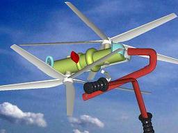
Take the Bourke engine, for instance:

Posted Image

(its controllable windows exe animation is at http://www.pattakon.com/pre/Bourke.exe )
There are many enthusiasts for the Bourke engine, and there was not a good, and easy to use, animation in the web. Now the animation talks for itself. The only you need are comments like: spot on the green yoke-roller-bearing, on the difficult task it has to accomplish because of the resulting load concentration etc.

Similarly, using the Commer TS animation I can simply say to 24gerrard:
Look at the blue rocker arms. It was the Achilles’ heel of the design, at least at the beginning.
Look the big red pins at the rocker arm centers: the force on each of them is double the combustion force.
Look at the wide angle each rocker arm performs per piston reciprocation.
Think the problems caused by the necessary big offset (normal to the plane of the image) of the two crankpins. The two pistons are coplanar while the two crankpins have some 50mm, or so, offset.
Look at the angle of the small connecting rods at the middle stroke.
Count the number of pins the force has to pass from the piston crown to arrive to the crankshaft.
Look how much space the crankshaft and the roots compressor occupy.
Etc.

The Commer TS is a well-balanced engine. The necessarily big mass of the blue rocker arms increases the inertia torque.
For symmetrical timing of the ports the PatOP and OPRE engines are perfectly balanced (the low-cost built-in volumetric piston-type scavenging-pump fits to the symmetrical timing) as regards the inertia forces and moments.

For applications wherein the OPRE engine:

Posted Image

drives a symmetrical load (a range extender, for instance, with two counter-rotating electric generators secured on its crankshafts, or a propulsion unit with two counter-rotating propellers secured on its crankshafts (for light airplanes, parapente, portable flyers etc) like:

Posted Image

the basis of the OPRE is not only perfectly rid of inertia vibrations of any kind (like the Wankel rotary engine and the luxury V12), but additionally it is perfectly rid of power pulses vibrations, too. The claim of FEV and AVL that their Wankel range extenders have the best NVH properties is wrong; the OPRE range extender can do better.


Lubrication.

If you want four-stroke-like lubricant-consumption in a two-stroke engine like the PatPOC or the OPOC, you need a good scrapper ring and no splash of oil on the top compression ring.

Take a modern car with a straight four, two liter, four stroke engine.
Say the engine works permanently at 2500 rpm and the car goes with 100 Km/h.
Say also it consumes 1 lit of lubricant per 20.000 Km (i.e. per 200 hours).
With 5lit/100 Km fuel consumption, for 20.000 Km the necessary fuel will be 1000 lit (fuel to lubricant consumption: 1000 to 1).

In an hour the engine rotates 2500*60 times.
In 200 hours the engine will rotate 2500*60*200 = 30.000.000 times

In the 1 lit of lubricant there are 1000cc, or 1.000.000 cubic mm.

I.e. per piston (there are four) and per reciprocation it is consumed ( 1.000.000 / 4 ) / 30.000.000, or 1/120 of a cubic mm.
For each cylinder, per 120 reciprocations, the scraper ring allows only 1 cubic mm to pass to the combustion chamber: i.e. you need 120.000 reciprocations to pass 1cc of oil towards the combustion chamber.


Unclematt:

“With regard to your scraper ring design, it would have to allow enough oil past itself to fill in the gap between liner and piston in order to be able to tranfer oil as you described in your last post.”

The engine doesn’t need to fill quickly the little gap between the scraper ring and the bottom compression ring. A tiny quantity of oil passes from the scraper ring per reciprocation and is added to the oil in the gap substituting the tiny quantity of oil removed by the compression ring.

Unclematt:

“I understand some oil slips by the scraper, flows along the piston skirt to the rings, and they spread it on the liner according to your description, but that seems a long route for the oil to take.”

At the BDC the distance from the scraper ring to the lower compression ring is less than 1mm. This is a short route for the oil to make.

Unclematt:

“I think I prefer the OPOC engine design, where oil is simply slung out of the scraper ring and onto the liner along the top of the cylinder.”

You prefer the OPOC oil control, so I can guess you understand how it works.

Can you, please, explain how it works in details, during the whole cycle?
For what oil consumption we talk about?
Does the OPOC need another scraper ring on the piston at the opposite direction, before the compression ring? If not, who prevents the oil slung out of the scraper ring to pass the compression rings and get into the combustion chamber?
When the piston decelerates near the BDC, who keeps the oil (slung at the opossite direction) from escaping to the port openings?
For what quantity of oil are we talking? If the quantity of oil is as small as calculated above, are you sure the OPOC oil control system can still works?

Also:

How the piston skirt is oiled in the oil-system of the OPOC?
And when the piston skirt thrusts heavily on the bridges between the ports, who keeps the oil between the piston and the liner from escaping to the ports?

I do need this info, because if the oil control of the OPOC is really better, we should ask them to let us use it in the PatPOC engine.

Wouldn't be easier, for you and me and anybody else, if EcoMotors had prepared an animation showing their OPOC oil control system?


Grumbles:

For the cooling of the exhaust piston of the OPRE and PatOP:

These engines are, by nature, of the crosshead architecture.
You don’t have a wrist pin below the piston crown, neither bosses to keep the wrist pin.
You don’t have a connecting rod to "hide" the piston crown.
The piston skirt does not take trust loads, so it remains significantly cooler, especially when it never touches the liner.
All these make the cooling of the exhaust piston quite easy.
Look at the exhaust piston of the PatOP prototype:

Posted Image

Near the BDC almost all the piston is in a strong air / oil stream coming from the crankcase (besides the two side hollow pistons there are four additional passages from the crankcase to the top cover of the engine).
The backside of the piston crown has nobody to restricts its cooling.

So, it is quite easy to keep the exhaust piston temperature as low as necessary.

On the other hand:

Instead of struggling to cool the pistons and the rest combustion chamber, isn’t it better to proactively keep the heat away from the pistons and the cylinders and the rest walls of the combustion chamber?

This way, not only more energy of the fuel becomes mechanical work (power, torque) but at the same time the cooling the pistons, of the oil, of the cylinder etc needs not be so extensive.


Thanks
Manolis Pattakos


#48 cheapracer

cheapracer
  • Member

  • 10,388 posts
  • Joined: May 07

Posted 27 March 2011 - 16:21

We did this back in the 70s on a BDA engine but I was never convinced the oil got where we wanted it to go because of the forces on the rod.


Oh really? Where did the oil go when it got to that pesky thing in the way called a gudgeon pin?

Have you thought about water cooling the piston with a cast in jacket and flexible feed?
Using flexible pipes, or perhaps sliding tubes with sealing rings.


Mr Spock used to say "Captain, whatever isn't impossible is possible" but otherwise it's an idea considered without any regard at all to the pyhsics of an engine. Could possibly work on a 900hp FF though.

Edited by cheapracer, 27 March 2011 - 16:43.


#49 cheapracer

cheapracer
  • Member

  • 10,388 posts
  • Joined: May 07

Posted 27 March 2011 - 16:32

Not sure why you say they are having "combustion troubles" with the OPOC engine because they have complete overlap between oil and compression rings...


I say it because they said it, not just in print either, I saw the guy actually say it during an interview. At the end of the day they still have the same combustion chamber shape as others did 70 years ago.

Manolis, no need to post more animations of various engines, though I know you love doing so.


Bite your tongue! Man I just love your animations, more I say! :up:


#50 unclematt

unclematt
  • Member

  • 146 posts
  • Joined: February 11

Posted 27 March 2011 - 16:44

Can you, please, explain how it works in details, during the whole cycle?
For what oil consumption we talk about?
Does the OPOC need another scraper ring on the piston at the opposite direction, before the compression ring? If not, who prevents the oil slung out of the scraper ring to pass the compression rings and get into the combustion chamber?
When the piston decelerates near the BDC, who keeps the oil (slung at the opossite direction) from escaping to the port openings?
For what quantity of oil are we talking? If the quantity of oil is as small as calculated above, are you sure the OPOC oil control system can still works?

Also:

How the piston skirt is oiled in the oil-system of the OPOC?
And when the piston skirt thrusts heavily on the bridges between the ports, who keeps the oil between the piston and the liner from escaping to the ports?

I do need this info, because if the oil control of the OPOC is really better, we should ask them to let us use it in the PatPOC engine.

Wouldn't be easier, for you and me and anybody else, if EcoMotors had prepared an animation showing their OPOC oil control system?

Why would OPOC create animations to give out that might compromise proprietary material? You and I might not mind showing people what we are up to, but some companies/people hold things a little closer to their vest. And I want to use their design in my engine, as you suggest you might have an interest.

And you can answer all of your questions if you read their patents. I use google to search the patent database. I already posted the patent in question about their on-piston scraper ring earlier in this thread. Did you read it?

You can also see the patent they hold on an in-liner scraper ring that seals the liner-to-piston gap below the ports. I am not at home, and don't have the file I can post this second, but I will try to find it and post it. It is a 2-piece ring design that sits in a groove in the liner a small distance "below" the outer ports.

Here, I think this is it LINK

Edited by unclematt, 27 March 2011 - 16:54.