I'm a novice. I know that the conversation of mass flow applies to a pipe with a thinner middle section. The diameter is smaller slow the volume of fluid that can flow through is smaller, but the flow speeds up to maintain the same flow rate through the whole pipe system. Do how does this relate to an Formula 1 car ? Does the bottom of an F1 car and the diffuser have the same volumetric flow rate ?
I know the diffuser slows down the speed of the airflow. By why is a bigger diffuser in terms of geometric volume better (such as the double diffuser)? This question has bothered me for some time.
Does a bigger diffuser speed up the airflow under the car ? Why ?
What fluid dynamics principles apply here ? What is the purpose of the tea tray splitter at the front ? Why is there no diffuser at the front of the car ?
Many thanks to all of you.

Diffuser Volume and Angle
Started by
pbukovca
, Jun 27 2012 03:54
33 replies to this topic
Advertisement
#2

Greg Locock
-

- 6,496 posts
- Joined: March 03
Member
Posted 27 June 2012 - 04:01
Do you feel like spending 30 bucks on katz? It really is a great book, and probably answers almost every practical question you can come up with using pencilCFD.
#3
MatsNorway
-

- 2,831 posts
- Joined: December 09
Member
Posted 27 June 2012 - 06:32
Why is there no diffuser at the front of the car ?
It has been made front diffusers for the Prototype cars. Lola i think pioneered it.
They also do it today. but in a different way, as the old design used the same air that went out at the back.
http://lemansprototy...1-69413568.html
http://lemansprototy...02-6139447.html
Thats why they lift a section of the front splitter.
F1 would have done this if they where allowed to have a wider nose/front.
The tea tray does at least stop air from being forced underneath the car.
Edited by MatsNorway, 27 June 2012 - 06:34.
#4
pbukovca
-
- 36 posts
- Joined: October 11
Member
Posted 27 June 2012 - 14:31
I plan to get the Katz book really soon. But I would appreciate some small details or explanation. Many thanks to all of you.
#5
Greg Locock
-
- 6,496 posts
- Joined: March 03
Member
Posted 29 June 2012 - 00:39
To answer your first post a bit more, draw a simple venturi, with intake, throat and exhaust. Use Bernouilli, incompressible gas, and constant mass flow rate at all sections. Now work out the downward pressure on the venturi, and fiddle around with the geometry.
I don't know what you mean by a double diffuser.
bear in mind you'll get separation at some critical angle of the exhaust, probably around 7 degrees, for the sake of argument.
I don't know what you mean by a double diffuser.
bear in mind you'll get separation at some critical angle of the exhaust, probably around 7 degrees, for the sake of argument.
#6
Monstrobolaxa
-

- 192 posts
- Joined: April 04
Member
Posted 29 June 2012 - 07:22
bear in mind you'll get separation at some critical angle of the exhaust, probably around 7 degrees, for the sake of argument.
6/7 degrees for 2D on a 3D with strakes you can go up to 16.7degrees.
#7
NeilR
-

- 623 posts
- Joined: October 09
Member
Posted 29 June 2012 - 11:18
is that 16+ deg assuming there is a great big low pressure from a wing near the outlet of the diffuser?
#8
pbukovca
-
- 36 posts
- Joined: October 11
Member
Posted 30 June 2012 - 08:28
How does constant mass flow rate work ? I mean specifically does the flow for the whole underfloor increase with a bigger diffuser or does the floor/venturi act a bottle neck that limits flow rate
no matter how much bigger the diffuser is made ? Like a pipe I mean ? Say 3 sectioned pipe with section 1 radius = 5 cm , section 2 radius = 2.5 cm and section 3 radius = 5 cm >> IF
increase section 3 radius to 7.5 cm will the constant mass flow rate for the whole pipe increase or will section 2 STILL act as bottle neck to limit flow ? Many thanks.
#9
Greg Locock
-
- 6,496 posts
- Joined: March 03
Member
Posted 30 June 2012 - 22:38
Slightly OT, have a read of this http://calteches.lib...28/2/Bettes.pdf
No it doesn't act as a bottle neck as such at typical racing speeds, but it will increase the duct drag, which you won't have in your model.
No it doesn't act as a bottle neck as such at typical racing speeds, but it will increase the duct drag, which you won't have in your model.
#10
bigleagueslider
-

- 1,235 posts
- Joined: March 11
Member
Posted 30 June 2012 - 23:30
How does constant mass flow rate work ? I mean specifically does the flow for the whole underfloor increase with a bigger diffuser or does the floor/venturi act a bottle neck that limits flow rate
no matter how much bigger the diffuser is made ? Like a pipe I mean ? Say 3 sectioned pipe with section 1 radius = 5 cm , section 2 radius = 2.5 cm and section 3 radius = 5 cm >> IF
increase section 3 radius to 7.5 cm will the constant mass flow rate for the whole pipe increase or will section 2 STILL act as bottle neck to limit flow ? Many thanks.
pbukovca-
The typical underbody diffuser on a race car functions like an extractor duct. It creates a region of low dynamic air pressure under the body.
Here's how they designed diffusers before PCs and CFD software:
http://hdl.handle.net/2060/19930083792
Regards,
Slider
#11
desmo
-

- 32,267 posts
- Joined: January 00
Tech Forum Host
Posted 01 July 2012 - 04:22
pbukovca-
The typical underbody diffuser on a race car functions like an extractor duct. It creates a region of low dynamic air pressure under the body.
Here's how they designed diffusers before PCs and CFD software:
http://hdl.handle.net/2060/19930083792
Regards,
Slider
Remarkable what was done with sliderule/analog tech.
#12
Greg Locock
-
- 6,496 posts
- Joined: March 03
Member
Posted 01 July 2012 - 04:39
Digging through old NACA reports is very interesting (and that one looks like a classic). Here's the NACA / NASA report server. http://ntrs.nasa.gov/?method=aboutntrs , not much is directly applicable to cars, but it is a great engineering resource.
#13
bigleagueslider
-
- 1,235 posts
- Joined: March 11
Member
Posted 01 July 2012 - 05:07
Remarkable what was done with sliderule/analog tech.
desmo,
That tech paper was written by a couple of Stanford University post grads. The founders of the Hewlett-Packard corporation were also both Stanford grads. I have an HP-15 engineering calculator that I still use every day, and it is over 25 years old. See the pattern here?
#14
desmo
-
- 32,267 posts
- Joined: January 00
Tech Forum Host
Posted 01 July 2012 - 05:34
My mother and father are both Stanford grads, as are a grandmother, a grandfather and even a great-grandmother who was in the first coed graduating class.

#15
carlt
-

- 4,169 posts
- Joined: June 09
Member
Posted 01 July 2012 - 20:12
Here's how they designed diffusers before PCs and CFD software:
http://hdl.handle.net/2060/19930083792
that was 1953 report
when was the first underbody aerodynamics in race car design ?
#16
carlt
-
- 4,169 posts
- Joined: June 09
Member
Posted 01 July 2012 - 22:02
some diffuser etc drawings [link was found on Nostalgia Forum - cutaway artists thread]
http://lemansprototypes.over-blog.it/
http://lemansprototypes.over-blog.it/
#17
bigleagueslider
-
- 1,235 posts
- Joined: March 11
Member
Posted 04 July 2012 - 02:35
My mother and father are both Stanford grads, as are a grandmother, a grandfather and even a great-grandmother who was in the first coed graduating class.
desmo,
The aerospace engineering company I currently work for actively recruits Stanford post grads. Stanford has a long history of producing a very high quality technical product. The university has also not given in to the disturbing recent trend among US universities of corrupting their science with political correctness.
slider
#18
Greg Locock
-
- 6,496 posts
- Joined: March 03
Member
Posted 04 July 2012 - 02:49
Every company I've ever worked for actively recruits my university's grads.
Odd that.
Odd that.
#19
Kelpiecross
-

- 1,730 posts
- Joined: October 10
Member
Posted 04 July 2012 - 04:34
[quote name='bigleagueslider' date='Jul 4 2012, 13:35' post='5801734']
desmo,
"recent trend among US universities of corrupting their science with political correctness."
What do you mean by this?
desmo,
"recent trend among US universities of corrupting their science with political correctness."
What do you mean by this?
Advertisement
#20
Greg Locock
-
- 6,496 posts
- Joined: March 03
Member
Posted 04 July 2012 - 05:37
How come the critical angle is bigger for a 3d venturi (a cone) than a 2d one (a wedge)?
Is there any benefit in smoothing the transition between the throat and the exhaust?
Is there any benefit in smoothing the transition between the throat and the exhaust?
Edited by Greg Locock, 04 July 2012 - 05:55.
#21
Monstrobolaxa
-
- 192 posts
- Joined: April 04
Member
Posted 04 July 2012 - 10:22
Sorry about the delay in replying.
Greg, yes smooth transition is better.
Read this: How wings work
It's a famous paper by Babinski. It explains the curved streamline theory.
Some at the top asked about if the 16.7 included the wing low pressure: No it does not. (check for a work by Andrea Ruhrmann, Uni of Southampton, PhD Thesis, for information on diffusers.
Greg concerning how come the critical angle is different I believe it has something to do with the vortices produced by the side of the diffuser tunnel and the strakes. The vortices induce upwash, which prevents the flow from separating from the diffuser surface. (my area is front wings not diffusers, but suspect that is what happens...).
Edited by Monstrobolaxa, 04 July 2012 - 10:22.
#22
bigleagueslider
-
- 1,235 posts
- Joined: March 11
Member
Posted 08 July 2012 - 00:55
Interesting paper.
These are few papers of a former lead aerodynamicist at Boeing, Arvel Gentry, who has been preaching the same in sailing in more layman terms:
The aerodynamics of sail boats are becoming quite complex. I know an aero guy that is working for a kiwi Americas' Cup team. He calls them wings instead of sails. It's amazing that these "sails" can push the boats downwind at speeds greater than the prevailing wind.
#23
Greg Locock
-
- 6,496 posts
- Joined: March 03
Member
Posted 08 July 2012 - 04:37
I thought we were talking about diffusers, not wings.
#24
Greg Locock
-
- 6,496 posts
- Joined: March 03
Member
Posted 08 July 2012 - 22:53
Excellent stuff. At first glance there is one piece of the puzzle left, influence of rear wing location on separation in the venturi. My guess is that the rear wing acclerates the flow in the venturi, ie reduces its deceleration, so you you should be able to carry a slightly higher angle without separation.
But, if the wing pulls too much extra air through under the car then the acceleration will increase and the critical angle will reduce.
Howver since the whole thing is a system you can't really break it down like that.
But, if the wing pulls too much extra air through under the car then the acceleration will increase and the critical angle will reduce.
Howver since the whole thing is a system you can't really break it down like that.
Edited by Greg Locock, 08 July 2012 - 22:59.
#25
Monstrobolaxa
-
- 192 posts
- Joined: April 04
Member
Posted 09 July 2012 - 07:15
I think, the guy you referring to, is Andreas Ruhrmann - short essay from his work can be found here
There were two people at Soton about that time.
Andrea Senior (female...who by marriage became Andrea Ruhrmann) who did a PhD on diffusers (I have a copy of her thesis in front of me) - I meant this one.
Andreas Ruhrmann (male) who also did research on diffusers!
Greg concerning you question: "are we talking about wings or diffusers?"
The paper I mentioned explains the transition from the flat bottom to the diffuser. And how being smooth and curved reduces the pressure in the transition. If it was sharp it would probably separate.
Edited by Monstrobolaxa, 09 July 2012 - 07:23.
#26
desmo
-
- 32,267 posts
- Joined: January 00
Tech Forum Host
Posted 09 July 2012 - 13:16
The paper can be downloaded here: http://core.kmi.open...ad/pdf/31565/34
#27
bigleagueslider
-
- 1,235 posts
- Joined: March 11
Member
Posted 10 July 2012 - 01:40
I thought we were talking about diffusers, not wings.
Fair enough. Race car diffusers it is then.
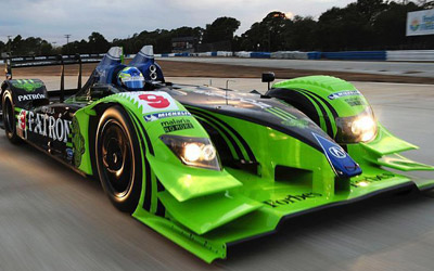
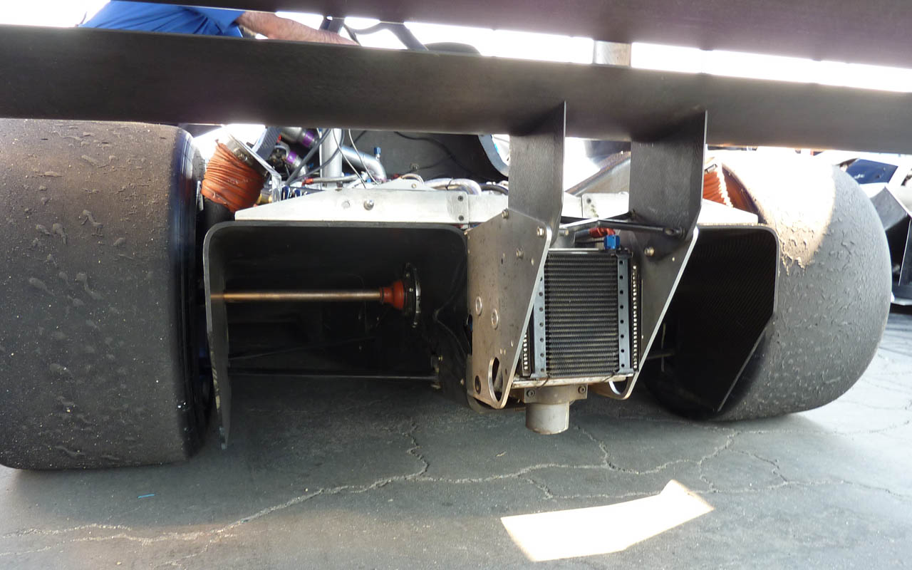
One question posed in the OP was the relationship between underbody diffuser volume and divergence angle. With F1 cars many of the basic diffuser dimensions are tightly regulated, so there's not a whole lot that can be done with the volume of the diffuser duct. However, if there were no such regulations there would be significant benefit to making the diffuser volume large. A good example is the IMSA GTP cars of the late '80s and early '90s. These cars used massive underbody tunnels. In fact, the tunnels were so tall that the lower wishbones and driveshafts passed through them. These cars made huge downforce from the underbody.
slider
#28
Greg Locock
-
- 6,496 posts
- Joined: March 03
Member
Posted 10 July 2012 - 22:38
I think the answer is that the fine detail of the underbody shape wouldn't make much odds. The reason I say that is that venturis are used all over the place, and yet their basic form, intake trumpet, parallel low pressure section, constant taper diffuser, scarcely varies. There is some variance in the trumpet design, but that Blair paper showed that at least on intake manifolds the gains from different shapes there were subtle at best.
#29
bigleagueslider
-
- 1,235 posts
- Joined: March 11
Member
Posted 12 July 2012 - 00:02
I think the answer is that the fine detail of the underbody shape wouldn't make much odds. The reason I say that is that venturis are used all over the place, and yet their basic form, intake trumpet, parallel low pressure section, constant taper diffuser, scarcely varies. There is some variance in the trumpet design, but that Blair paper showed that at least on intake manifolds the gains from different shapes there were subtle at best.
That's true in some respects. Some types of diffuser designs are less problematic than others. One thing that makes diffuser design more/less difficult is what occurs ahead or behind the diffuser section. In this respect, an intake manifold or carb venturi is different from a radiator duct or an underbody.
Race car underbody diffuser design also presents a unique challenge in that one of the four walls of the diffuser duct is formed by the track surface. Three of the duct walls are moving relative to the airflow, and one is not. That certainly throws a monkey wrench into things.
slider
#30
MatsNorway
-
- 2,831 posts
- Joined: December 09
Member
Posted 12 July 2012 - 07:02
It might give new challenges in calculations considering the wall moves up and down. But it proably gives gains over a fully static one because the lower wall aids in moving the air. Rather than generate a umm. a boundary layer?
Edited by MatsNorway, 12 July 2012 - 07:06.
#31
bigleagueslider
-
- 1,235 posts
- Joined: March 11
Member
Posted 14 July 2012 - 00:16
It might give new challenges in calculations considering the wall moves up and down. But it proably gives gains over a fully static one because the lower wall aids in moving the air. Rather than generate a umm. a boundary layer?
For being such a small portion of the total airflow those pesky boundary layers sure do have a big effect. Whether it's aerodynamic lift/drag or convective heat transfer, all of the real activity takes place in that tiny boundary layer flow. Whether this boundary layer flow is turbulent or laminar can have a big effect on L/D or heat transfer rate. It's a similar situation to that of the tiny tire contact patches. No matter how good the engine, suspension, brakes, aerodynamics, etc. of the car are, in the end it all boils down to how effective those four tiny tire contact patches are. The tire contact patches are the only interface to the track, and the boundary layer is the only contact with a heat exchanger fin, duct wall or wing surface.
#32
NeilR
-
- 623 posts
- Joined: October 09
Member
Posted 14 July 2012 - 01:55
I suspect that the Re of the duct is such that the flow is turbulent, but that the effort is put in to make sure it is well formed.
#33
MatsNorway
-
- 2,831 posts
- Joined: December 09
Member
Posted 17 July 2012 - 17:53
http://www.youtube.c...eature=youtu.be
Small video of a diffuser like shape in Autodesk Falcon.
Small video of a diffuser like shape in Autodesk Falcon.
Edited by MatsNorway, 26 July 2012 - 11:49.
#34
MatsNorway
-
- 2,831 posts
- Joined: December 09
Member
Posted 26 July 2012 - 11:49
Another and better one.


