Jump to content


Photo
* * * * * 1 votes

Flat Eight Porsche Engines


  • Please log in to reply
64 replies to this topic

#1 rory57

rory57
  • Member

  • 98 posts
  • Joined: November 10

Posted 16 July 2013 - 11:19

Flat Eight Engines

There haven’t been many of these; aero engines from Lycoming and Continental and from Porsche, the 1.5litre F1 and the later Sports Car racing engines of the 1960s.
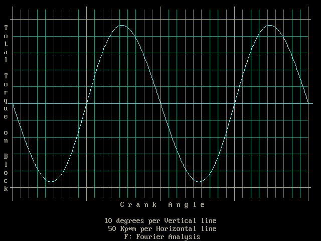
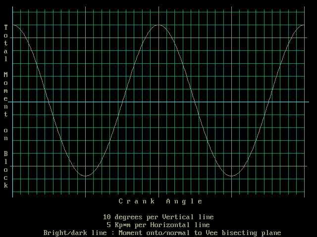
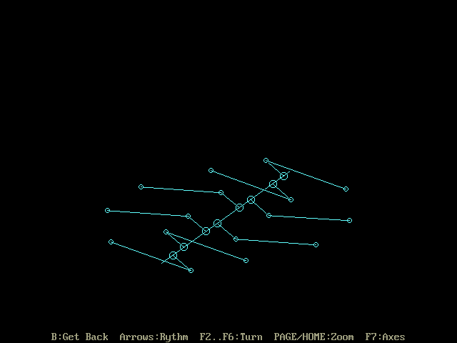
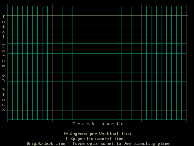
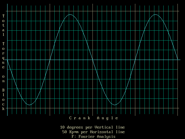
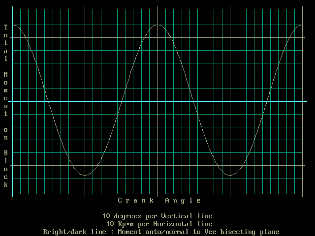
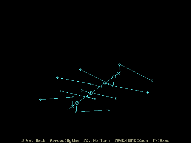
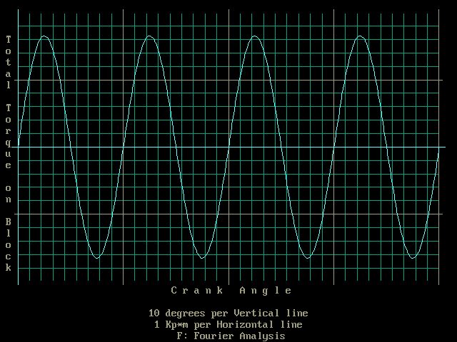
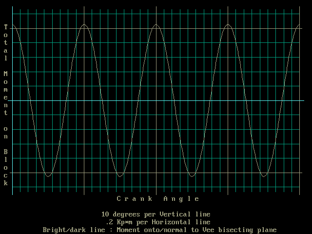
They are usually referred to as “boxer” engines, implying that the horizontally (almost) opposite cylinders each had it’s own crank throw and that these throws were 180˚ apart such that both pistons are at TDC / BDC simultaneously, "punching like a boxer" (?)
However flat 12 engines are also referred to as “Boxer” engines and I have never read of one of those with such a (12 throw) crank.

My question is, what crankshaft configuration did these Porsche flat 8 racing engines use?

The Boxer configuration, whilst obviously the best from the point of view of refinement, is not essential. For instance, a flat plane four throw crankshaft as for an inline four would give perfect primary and secondary balance but cylinders would fire in pairs. Possibly quite acceptable for a 1.5 litre F1 engine. A cross-plane crank like a regular V8 would need the extra balance weights that a V8 needs and would have a similar uneven firing order for each bank (compromising exhaust design).

There are some references out there on the web to engine balance problems with the 908 sports car engine and that these were cured with a change of firing order. Anyone know what was really going on there?

Edited by rory57, 16 July 2013 - 11:21.


Advertisement

#2 manolis

manolis
  • Member

  • 935 posts
  • Joined: May 03

Posted 16 July 2013 - 17:54

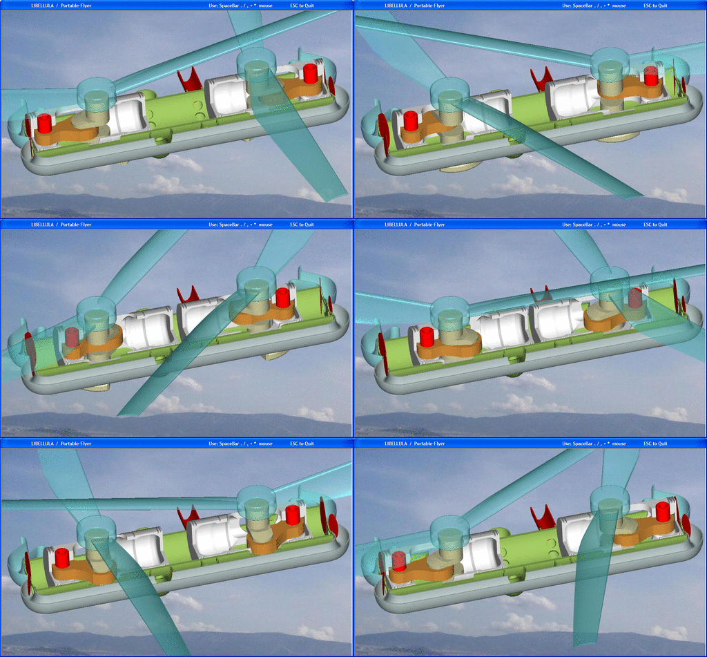
Flat Eight Engines

A cross-plane crank like a regular V8 would need the extra balance weights that a V8 needs and would have a similar uneven firing order for each bank (compromising exhaust design).


Rory57,

A flat-8 with cross-plane crankshaft needs more than the balance webs of the regular V-8.
It needs balance webs on the crankshaft, it also needs an additional counter-rotating balancing shaft.
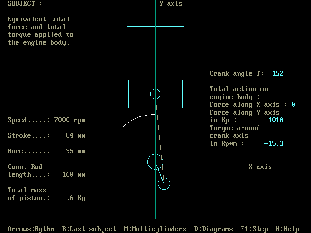
The balance.exe program at the Teaching section of the www.pattakon.com web site helps.

The flat-8 with the plane four-throw crankshaft has perfect balance of the inertia forces, however it has a strong 2nd order inertia torque (i.e. inertia moment about the crankshaft axis); when one piston is at the TDC, every piston has zero speed, i.e. zero kinetic energy; eighty about ninety crankshaft degrees later the kinetic energy of the eight pistons maximizes.
The offset between the neighboring connecting rods of the flat-8 with the plane four-throw crankshaft, causes an unbalanced inertia moment of 2nd order.

Thanks
Manolis Pattakos

Edited by manolis, 18 July 2013 - 02:34.


#3 rory57

rory57
  • Member

  • 98 posts
  • Joined: November 10

Posted 16 July 2013 - 19:41

Remembered Karl Ludvigsens "Classic Racing Engines". He makes clear that the Porsche F1 flat eight was a true boxer engine with an eight throw crank.

Info. regarding the later sports racing engines (and any other flat eights) sill sought.

Manolis: thank you for the correction. More study required!


#4 Henri Greuter

Henri Greuter
  • Member

  • 13,342 posts
  • Joined: June 02

Posted 21 July 2013 - 10:06

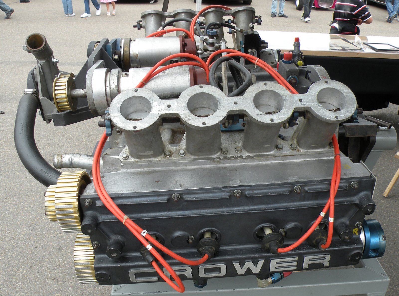
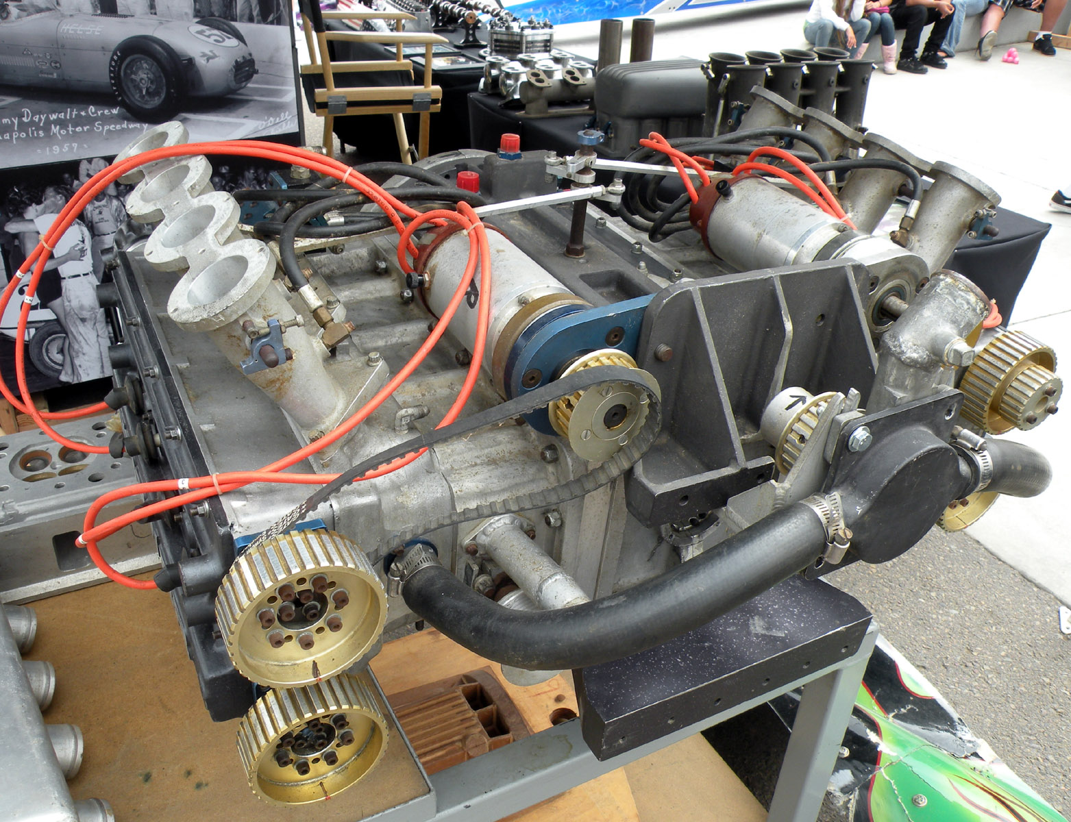
There was a new Flat eight introduced at Indianapolis in 1977, the Crower. It used a purpuse design crankcase on which two cylinderheads of the Chevolet Vega engine were mounted. Bob Bubenik and Bruce Crower were behind it. Not much known about the engine other then that the flat lay-out of the engine didn't suit the cylinderheads of Vega heritage.
Never saw a picture of it other the one in the 1977 Hungness yearbook and since I hate to copy without approval I won't reproduce it here. Sorry.

Henri

Edited by Henri Greuter, 21 July 2013 - 10:08.


#5 desmo

desmo
  • Tech Forum Host

  • 31,247 posts
  • Joined: January 00

Posted 21 July 2013 - 15:03

There was a new Flat eight introduced at Indianapolis in 1977, the Crower. It used a purpuse design crankcase on which two cylinderheads of the Chevolet Vega engine were mounted. Bob Bubenik and Bruce Crower were behind it. Not much known about the engine other then that the flat lay-out of the engine didn't suit the cylinderheads of Vega heritage.
Never saw a picture of it other the one in the 1977 Hungness yearbook and since I hate to copy without approval I won't reproduce it here. Sorry.

Henri


Posted Image


Posted Image

From this page-- http://justacarguy.b...crower-1st.html

#6 Henri Greuter

Henri Greuter
  • Member

  • 13,342 posts
  • Joined: June 02

Posted 22 July 2013 - 16:37

From this page-- http://justacarguy.b...crower-1st.html


Nice find!

Henri

#7 WhiteBlue

WhiteBlue
  • Member

  • 2,188 posts
  • Joined: July 10

Posted 22 July 2013 - 17:57

The flat Porsche engines have an impressive history but I would have doubts that they will be repeated in the current race car formulae like F1 or LMP1. Not really good for aerodynamic packaging would be the most important reason for that.

#8 Lee200

Lee200
  • Member

  • 58 posts
  • Joined: December 07

Posted 02 August 2013 - 19:08

Flat Eight Engines
My question is, what crankshaft configuration did these Porsche flat 8 racing engines use?


Rory, I researched this a few years ago and came to the conclusion that the Porsche flat 8 engines were true boxers in that each piston had it's own crankpin. I'm fairly certain the P910 2.2 liter and the final P908 3.0 liter engines were this way. I think the P804 1.5 liter F1 engine was too. But I'm not at all certain about the initial versions of the P908 3.0 liter engine.

I'm still confused about which crankshaft configuration the different engines used. Apparently there were two possibilities.

1. Two flat plane, 4 crankpin crankshafts connected end to end with a 90 degree offset.
2. One flat plane, 4 crankpin crankshaft in the center with half of the same crankshaft connected on each end, but each with a 90 degree offset from the center.

I think all the engines used the first configuration, but am not at all sure now; especially with the P908 as it changed its firing order twice. According to Bill Oursler, the P908 firing orders were:

1--1,8,2,6,4,5,3,7; bad vibrations with 135 or 225 degrees between opposite pistons
2--1,5,2,7,4,8,3,6; better, but still had vibrations
3--1,7,2,8,5,3,6,4; final version that eliminated vibrations; a true boxer with 180 degrees between opposite pistons

Supposedly at one time there was a photo of the P908 flat 8 crankshaft on the web, but I've never found it.

I was surprised to learn too that the famous P917 flat 12 engine was not a true boxer as two pistons shared each crankpin. This of course allowed for a shorter crankshaft and engine.

It's been a while since I researched this so would like to hear thoughts from others who might have better information.

#9 TDIMeister

TDIMeister
  • Member

  • 318 posts
  • Joined: January 06

Posted 16 August 2013 - 18:38

A horizontally opposed 8-cylinder engine with either shared or 180° crankpins on the opposing banks (a true boxer) and flat-plane crank would result in 4 cylinders at once reaching TDC and BDC simultaneously, resulting in 2 cylinders firing at the same time. Not impossible, but unlikely either due to a multitude of reasons, not the least of which the inertial torques. The Ferarri Testarossa 12-cyl engine, being HO with shared crankpins (essentially making it a 180° vee rather than a Boxer), would not have had this problem.

Edit: there are 3 principle variants of 8-cylinder HO layouts that are possible with even firing intervals - not all of these have been given equal treatment in the discussion:
1) Flat-plane crank, shared crankpins, essentially 2 conventional 4-cylinder engines mirrored (the aforementioed "180° vee" with the 4 pistons reaching TDC and BDC simultaneously)
2) Flat-plane crank, opposed crankpins (8 throws total 180 degrees apart per opposed bank, a true Boxer), but same situation of 4 pistons @ TDC and 4 @ BDC, just different ones as 1) above
3) Cross-plane crank, 8 separate throws 90 or 270 degrees apart per opposed bank, could be arranged any of a multitude of ways.

1) above would have no free forces but secondary out-of-balance typical of a inline 4-cylinder engine (actually 2X more). Inertia torques also bad due to pistons stopping at the same time at TDC and BDC
2) above would be balanced for primary and secondary forces but also have high inertia torques
3) depending on crankpin arrangement could be balanced for forces but leave unresolved primary and secondary yawing moments. However, inertial torques are the most favourable.

3) is the most likely for the Porsche engine but doing an FFT of the exhaust sound would be the quickest way to find out if this is the case. 1) and 2) would result in half as frequent power - and therefore exhaust - strokes as 3).

Edited by TDIMeister, 16 August 2013 - 19:14.


#10 PJGD

PJGD
  • Member

  • 153 posts
  • Joined: April 04

Posted 17 August 2013 - 00:41

I respect TDIMeister's posts; he normally knows what he is talking about, however I do get peeved when people subscribe to the notion that HO engines are either a Boxer or a 180° Vee layout because it does not seem to leave room for, or have a satisfactory name for engines that combine both separate and paired crank throws. Such engines are neither one nor t'other; so what are they?

Yes, the example that I am giving below is a pre-war non-high performance 2-bearing crank flat four, which in a modern incarnation would have a 4-bearing crankshaft as in GB2426550, but nevertheless some recognition should be given to the fact that this geometry does not abide by the common definition and yet is a valid arrangement that could be made in flat-8 format, either flat or cross-plain. Perhaps it is just semantics since at the end of the day there may be no substantive difference in how the engine runs, but it will be a little bit shorter.

Posted Image

PJGD

#11 TDIMeister

TDIMeister
  • Member

  • 318 posts
  • Joined: January 06

Posted 17 August 2013 - 01:10

@PJGD, I respect your posts too and apologise that I admittedly do not have an encyclopedic knowledge of every single engine ever made. As a 4 cylinder engine as your picture illustrates, there are only a limited number of possibilities of plausible and sensical crankpin arrangements and, I'll demonstrate my ignorance again in that by not seeing better detail of the crankshaft itself or reciprocating group, I can only surmise from observation that - numbering cylinders from 1-4 according to chain-end back) - #1 (right bank) is on its own crankpin; #2 and #3 are shared 180° from #1, although the pistons are opposed; and #4 (left bank) is on its own crankpin on the same position as #1. I'd call it a Boxer; sorry if you don't agree. Main bearing count doesn't doesn't change this classification. If you don't agree, simply view a Subaru boxer crank and imagine deleting the inner 3 main bearings and their associated webs.

Posted Image

Posted Image


Respectfully.

Edit: Before I get impugned for any oversight, the second picture with the con rods mislead the viewer. It is properly arranged thus:

Posted Image

Therefore it essentially the same as PJDG's example. What distinguishes a Boxer engine from a 180° Vee engine is less about the physical assignments of the pistons to crankpins vis-à-vis shared vs. offset/opposed, but rather more about the resulting firing order and engine balance.

Edited by TDIMeister, 17 August 2013 - 01:24.


#12 PJGD

PJGD
  • Member

  • 153 posts
  • Joined: April 04

Posted 17 August 2013 - 03:57

OK, yes I am with you; my old example should rightly be considered a boxer even though the center crankpin is shared - that is not the defining feature; firing order is more important.

Firing order in this conventional boxer example below is: 1423

Posted Image

PJGD


#13 bigleagueslider

bigleagueslider
  • Member

  • 1,235 posts
  • Joined: March 11

Posted 17 August 2013 - 05:22

I don't know German, so I can't say for sure what this drawing describes. But the diagram in the lower right corner seems to indicate the 908 crank used a pair of 4 pin cranks with each having 180deg spacing, and that were mounted front/rear and indexed by 90deg.

Posted Image

#14 manolis

manolis
  • Member

  • 935 posts
  • Joined: May 03

Posted 17 August 2013 - 06:39

. . .
Edit: there are 3 principle variants of 8-cylinder HO layouts that are possible with even firing intervals - not all of these have been given equal treatment in the discussion:
1) Flat-plane crank, shared crankpins, essentially 2 conventional 4-cylinder engines mirrored (the aforementioed "180° vee" with the 4 pistons reaching TDC and BDC simultaneously)
2) Flat-plane crank, opposed crankpins (8 throws total 180 degrees apart per opposed bank, a true Boxer), but same situation of 4 pistons @ TDC and 4 @ BDC, just different ones as 1) above
3) Cross-plane crank, 8 separate throws 90 or 270 degrees apart per opposed bank, could be arranged any of a multitude of ways.

1) above would have no free forces but secondary out-of-balance typical of a inline 4-cylinder engine (actually 2X more). Inertia torques also bad due to pistons stopping at the same time at TDC and BDC
2) above would be balanced for primary and secondary forces but also have high inertia torques
3) depending on crankpin arrangement could be balanced for forces but leave unresolved primary and secondary yawing moments. However, inertial torques are the most favourable.

3) is the most likely for the Porsche engine but doing an FFT of the exhaust sound would be the quickest way to find out if this is the case. 1) and 2) would result in half as frequent power - and therefore exhaust - strokes as 3).


TDIMesiter,
according the balance.exe program at the Teaching section of the pattakon web site, there are a few mistakes in your post:

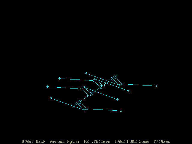
Here is your arrangement no 1:

Posted Image

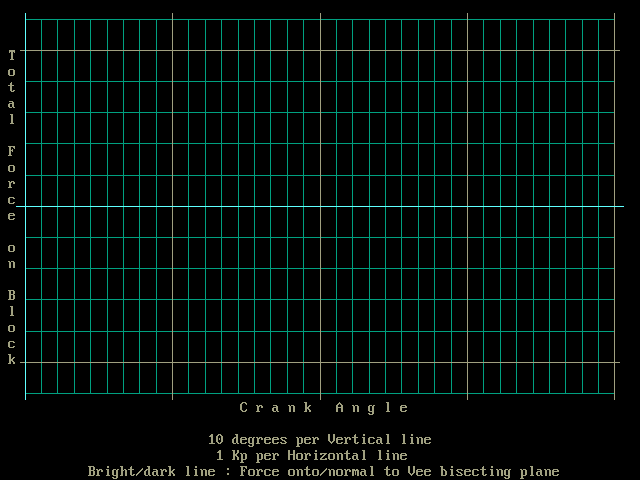
The plot of the inertia forces versus the crankshaft angle is:

Posted Image

the inertia torques plot is:

Posted Image

the inertia moments plot is:

Posted Image

In the above eight cylinder with the plane crank and the shared crankpins there is no "secondary out-of-balance typical of a inline 4-cylinder engine (actually 2X more)".

If someone wants to better understand why this happens:
when two pistons are reciprocating in coaxial opposed cylinders sharing the same crankpin, the center of gravity of the two pistons is at the projection of the crankpin center onto the cylinder axis (geometrical symmetry), i.e. the center of gravity of the two pistons performs a pure sinusoidal (or harmonic) motion (first order only).
I.e. the inertia force from each pair of pistons is of first order only.
I.e. there is no case of unbalanced 2nd order forces in your no 1 arrangement of the flat eight.
In case the two opposed cylinders have an offset (not "forked" connecting rods), the inertia force remains the same; what changes is that an inertia moment is generated.


Here is your no 2 arrangement for comparison:

Posted Image

Posted Image

Posted Image

Posted Image

the bigger offset of the opposed cylinders causes a stronger inertia monent, i.e. the no2 arrangement is less "vibration free" than the no1 arrangement.
Besides, the crankshaft of the no1 is way stronger and lighter.
I.e. the no1 arrangement is better than the no2 from every point of view.

But both, the no1 and no2 arrangements are non-even firing.


Here is your an arrangement according your no 3:

Posted Image

Posted Image

Posted Image

Posted Image

There is a weak inertia torque as you write; it is of fourth order.

There is a negligible inertia moment (of fourth order, too).
Ii.e. your "depending on crankpin arrangement could be balanced for forces but leave unresolved primary and secondary yawing moments" is wrong.

This arrangement (no3, with the crankpins at (0, 180), (90, 270), (270, 90), (180, 0) crank degrees) is even firing. The problem is the torsional strength of the crankshaft.

Thanks
Manolis Pattakos


#15 TDIMeister

TDIMeister
  • Member

  • 318 posts
  • Joined: January 06

Posted 17 August 2013 - 15:15

I don't know German, so I can't say for sure what this drawing describes. But the diagram in the lower right corner seems to indicate the 908 crank used a pair of 4 pin cranks with each having 180deg spacing, and that were mounted front/rear and indexed by 90deg.

Posted Image

From top to bottom, the text reads (simplified translation; I am not a professional translator)

Firing order 908 | Firing interval 90° {This alone tells me a lot - that it's even firing, which narrows down possible crank layouts significantly}

908 1st firing order | (Kw = Kurbelwelle > crankshaft; Hubz = Hubzapfen > crankpin; versetzt = offset/staggered)
Mass balancing very bad

908 2nd firing order | Same crankshaft and {NaK unknown} (W = Winkel > angle)
Mass balancing very bad

908 different crankshaft | 2X4 crankpins in 1 (Ebene = level/plane)

Commentary: From the last entry and the sketches of the firing order and crankpin arrangements, it is apparent to me that the 908 crank has the front set of 4 crankpins in one plane and the rear 4 on the normal plane to the first. The firing order bears this out. A first look at the crankshaft sketch would seem to suggest that all crankpins are on a single plane, leading to the #2 scenario in my first post above, but then the firing order and interval would not be correct.

Edited by TDIMeister, 17 August 2013 - 15:16.


#16 TDIMeister

TDIMeister
  • Member

  • 318 posts
  • Joined: January 06

Posted 17 August 2013 - 16:20

TDIMesiter,
according the balance.exe program at the Teaching section of the pattakon web site, there are a few mistakes in your post:
...
In the above eight cylinder with the plane crank and the shared crankpins there is no "secondary out-of-balance typical of a inline 4-cylinder engine (actually 2X more)".

In the convention with which I have been trained, I lump together unresolved forces AND moments in calling a layout balanced or not. If EITHER forces or moments of any order - particularly the first two - are non-zero, I consider the layout as unbalanced. You appear to employ the convention of considering only the forces. It is not incorrect and neither is my employed convention, only a question of definition and semantics. You show a second order moment and that is consistent with my statement of a secondary out-of-balance but since we're nit-picking about semantics, I retract the statement, "typical of a inline 4-cylinder engine (actually 2X more)" since a 4-cylinder has unresolved 2nd order forces, not moments.

An inline-5 engine (1-2-4-5-3) is balanced for forces in the 1st and 2nd orders but have unresolved moments in both the 1st and 2nd orders. I also call this layout unbalanced. (source, see Table 1; I can do the math too - it's just that as I've said to you many times, I cannot run your balance.exe program in Windows 7.)

If someone wants to better understand why this happens:
when two pistons are reciprocating in coaxial opposed cylinders sharing the same crankpin, the center of gravity of the two pistons is at the projection of the crankpin center onto the cylinder axis (geometrical symmetry), i.e. the center of gravity of the two pistons performs a pure sinusoidal (or harmonic) motion (first order only).
I.e. the inertia force from each pair of pistons is of first order only.
I.e. there is no case of unbalanced 2nd order forces in your no 1 arrangement of the flat eight.
In case the two opposed cylinders have an offset (not "forked" connecting rods), the inertia force remains the same; what changes is that an inertia moment is generated.

No disagreement here, only in semantics of what defines balance.

the bigger offset of the opposed cylinders causes a stronger inertia monent, i.e. the no2 arrangement is less "vibration free" than the no1 arrangement.
Besides, the crankshaft of the no1 is way stronger and lighter.
I.e. the no1 arrangement is better than the no2 from every point of view.

I understand why you placed a bigger offset for no2 - to allow for the widths of the webs and/or main bearing (where applicable) between adjacent crankpins. However, this is deceptive for a non-expert who only sees pictures and reads values off graphs but don't understand the underlying physics, and it mathematically changes the context of the point I am trying to make. If you set the offsets the same between no1 and no2 - so that we're ONLY comparing the merits of the crankpin arrangements and not of the offsets, all else being equal - the magnitudes of the moments should become equal (I didn't do the calculations, but I'd welcome the enlightenment). The leads to another point. Your calculations from your program considers forces and moments from an external frame of reference, i.e. the forces/moments/torques experienced outside the engine, which would get transmitted to the mounts and the rest of the chassis/drivertain. However, you completely ignore INTERNAL mass and gas forces acting WITHIN the crankshaft before you prematurely make the generalisation that I.e. the no1 arrangement is better than the no2 from every point of view. I recall an argument on TDIClub where you excoriated a comment I made about one of your engine designs being "under-supported." We come full-circle again because it seems after all this you have not learned about internal vs. external forces.

There is a weak inertia torque as you write; it is of fourth order.

There is a negligible inertia moment (of fourth order, too).
Ii.e. your "depending on crankpin arrangement could be balanced for forces but leave unresolved primary and secondary yawing moments" is wrong.

Of course you would come to the conclusion that I'm wrong, because the ONE layout that you chose to analyse and illustrate, whether intentional or by dumb luck, happens already to be the one to give a good result. As I have stated, there are multiple possibilities for staggered, cross-plane crankpin layouts, and some of these COULD - and DO - leave unresolved primary and secondary yawing moments. Go ahead and run your balance.exe program on every combination, post the results and prove me wrong by showing that not a single one could have an unresolved out-of-balance (remember my convention of considering BOTH forces AND moments) as I contend. The sketch posted by bigleagueslider would be the perfect exercise for you to analyse, since whoever sketched it agreed with me that the mass balancing on the first two scenarios are very bad.

This arrangement (no3, with the crankpins at (0, 180), (90, 270), (270, 90), (180, 0) crank degrees) is even firing. The problem is the torsional strength of the crankshaft.

Oh wow, maybe I am wrong; you have an appreciation for crankshaft torsional strength, which are excited from internal crankshaft forces.;)

Listen Manolis, is seems we have gotten on a bad footing over the years over more than one forum. I think we can do a lot more to put our minds together in a spirit of co-operation and goodwill instead of trying to nit-pick and correct each other.

Edited by TDIMeister, 17 August 2013 - 18:19.


#17 rory57

rory57
  • Member

  • 98 posts
  • Joined: November 10

Posted 17 August 2013 - 17:35

Flat eight does look a bit like a challenge without sufficient reward. The more I think about it, the worse it seems.
The arrangement identified in the sketches as two single plane four cylinder cranks at 90 degrees has nine main bearings, more than any flat 12! Annoyingly, it is easy to find images of the 917 / flat-12 crank about which there is no doubt or controversy.

IF a flat-eight was made with a four-throw single-plane crank this would give a poor inertia torque / moment result but good balance. OK, I follow that, it is well explained above.
My question is, would the inertia torque / moment be any worse therefore any more of a problem than for a four cylinder engine of the same capacity? It seems to me not. It would I think give an engine with the power potential and costs of an eight and the refinement of a flat-four. Any thoughts?

#18 TDIMeister

TDIMeister
  • Member

  • 318 posts
  • Joined: January 06

Posted 17 August 2013 - 21:12

Posted Image

Posted Image

Posted Image

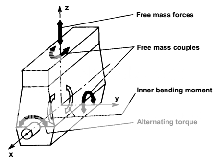
One other thing: if I interpret correctly, "Force (or Moment) onto/normal to Vee bisecting plane" in your graphs, by the convention of the illustration below - x-z being your bisecting plane in both cases - you are only considering Fy (horizontal shake) and My (pitching moment/couple) and not the other modes Fz (vertical shake) and Mz (yawing moment/couple). Since you're very good at giving homework to others to use your balance.exe program, I have a task for you: please also perform your analyses of No1, No2, No3, as well as all future analyses to calculate Fz and Mz also.

Posted Image

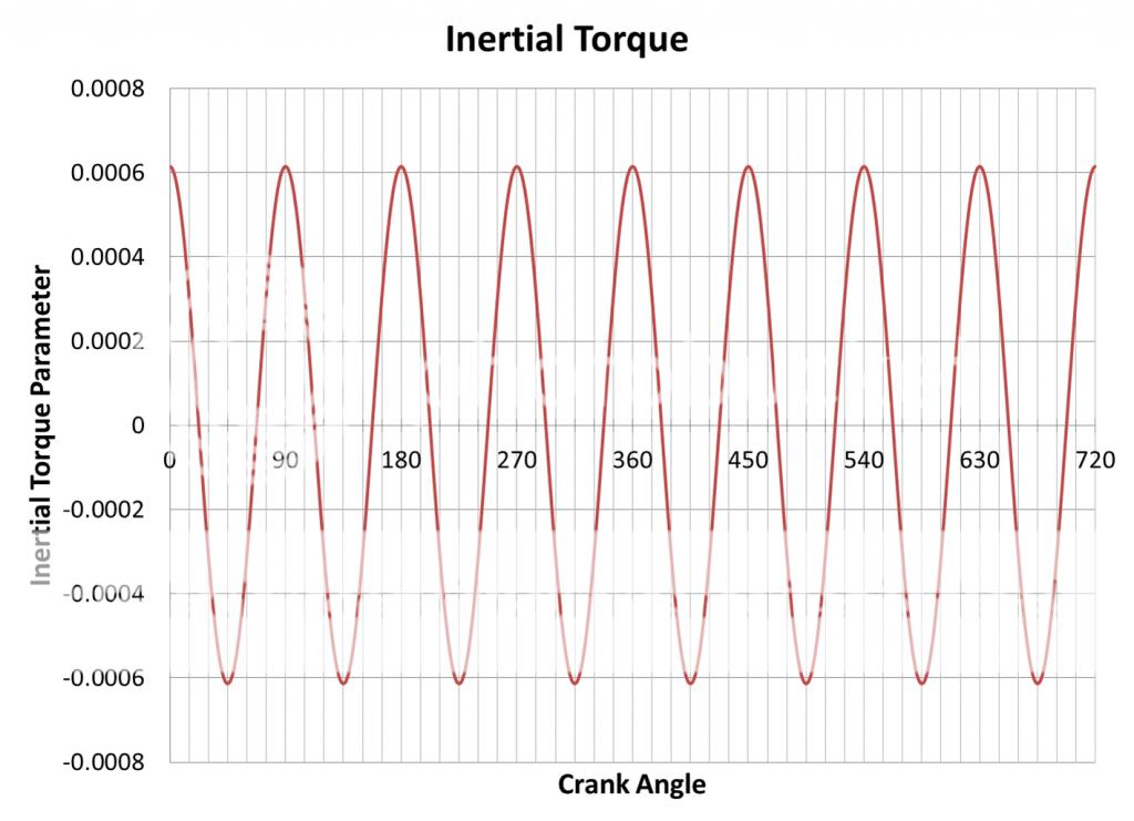
I also have my own spreadsheet to calculate inertial torque, below for an inline-8 engine (I haven't tried to do it with Vee angles but it can be done). The y-axis is simply called an "Inertial Torque Parameter" because it is not a torque in Nm or lb ft, since reciprocating masses are unknown and made into a unit magnitude, it is just a function of acceleration. (M = r x F; F = ma). One can see the same 4th order behaviour.

Posted Image

Edited by TDIMeister, 17 August 2013 - 22:25.


#19 TDIMeister

TDIMeister
  • Member

  • 318 posts
  • Joined: January 06

Posted 18 August 2013 - 00:02

IF a flat-eight was made with a four-throw single-plane crank this would give a poor inertia torque / moment result but good balance. OK, I follow that, it is well explained above.
My question is, would the inertia torque / moment be any worse therefore any more of a problem than for a four cylinder engine of the same capacity? It seems to me not. It would I think give an engine with the power potential and costs of an eight and the refinement of a flat-four. Any thoughts?

Rory, Manolis will be able to give you a much more quantitatively precise answer to your question from a mass balance standpoint using his software program. However, a complete evaluation of "balance" and NVH characteristics must encompass a holistic consideration of both inertial and gas-force excitations caused by the combustion events, and the discussion thus far has been limited only to the former. A 4-cylinder boxer will exhibit mass-balancing properties as listed in Table 1 here. Compared to an 8-cylinder of the same displacement, this will give rise to certain advantages and disadvantages. Advantages being generally lower FMEP, less weight and and shorter length (but not 1/2 as long). However, half as frequent combustion events will result in a lack of power stroke overlap, giving rise to high gas-force torque fluctuations (see here). Also, an engine with large individual cylinder dimensions and relatively few cylinders will result in higher HP per cylinder (and furthermore at a generally lower RPM to maintain a limited mean piston speed), higher per-piston heat flux, higher piston/head bolt stresses and also larger package due to the required bore, stroke and con rod length. A boxer-6 would be an excellent compromise, being balanced for forces and moments in the first and second orders, exhibiting good inertia torque characteristics and having power stroke overlap that lies between an 8 and 4 cylinder engine.

Edited by TDIMeister, 18 August 2013 - 00:13.


Advertisement

#20 manolis

manolis
  • Member

  • 935 posts
  • Joined: May 03

Posted 18 August 2013 - 08:30

I also have my own spreadsheet to calculate inertial torque, below for an inline-8 engine (I haven't tried to do it with Vee angles but it can be done). The y-axis is simply called an "Inertial Torque Parameter" because it is not a torque in Nm or lb ft, since reciprocating masses are unknown and made into a unit magnitude, it is just a function of acceleration. (M = r x F; F = ma). One can see the same 4th order behaviour.


TDIMeister,

The inertia torque of every even firing eight cylinder arrangement (same pistons, same stroke, same connecting rods, same rpm etc) is the same (in-line, flat, boxer, V-90, V60 etc). So you don't need to make other calculations; you already have the plot.

Similarly, the inertia torque of all even firing four-cylinders is the same.
Similarly the inertia torque of all even firing six cylinders is the same.

Just look the inertia torque from the energy view point. The inertia torque provides to the set of the pistons the necessary energy in order to move as they move.


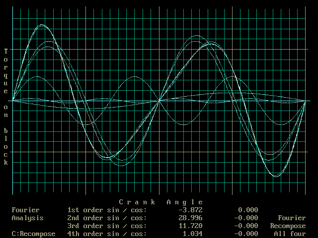
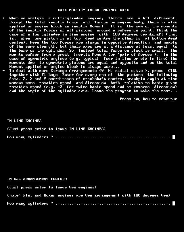
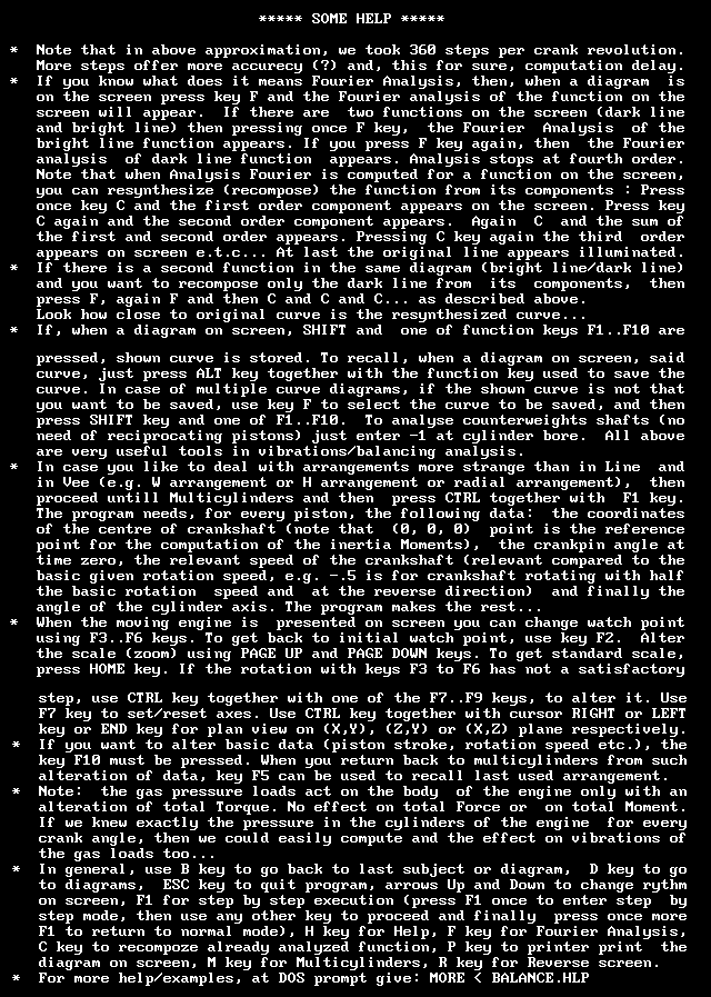
I think the following screens from the balance.exe program will help those who want to understand how things are working and are calculated.

Posted Image

Posted Image

Posted Image

Posted Image

Posted Image

Posted Image

Posted Image

Posted Image

Posted Image

Posted Image

Posted Image

Posted Image

As you see, the necessary data are the fewest possible: stroke, reciprocating mass, connecting rod length, rpm and arrangement.

For comparison, imagine the quantity of the necessary data in the case you need to find out the effect of the gas pressure (at what engine load?) on the vibrations of the engine.
You need to provide the cylinder pressure vs the crank angle.
Knowing the cylinder pressure, one can add to the inertia torque the gas pressure torque in order to take the total torque.
The Total Force and Total Moment on the engine block are not effected.
Then you have to repeat the calculations for every engine load.
Then you can extend the calculations for the case of transient conditions. And so on.
Does the "pain worth the gain"?

Similarly, if you need to find the effect of the elasticity of the parts (connecting rods, crankshaft, casing etc) on the vibrations, you need to provide the necessary data which deffer from engine to engine. Depending on the design of the crankshaft, a phase difference (from the geometrically correct) can result between the first cylinder and the last cylinder.

Similarly, if you need to calculate the effect of the clearance between the piston and the liner on the vibrations, you need a lot of additional data and a lot of assumptions.

It is already difficult for most engineers / mechanics to understand / calculate the basics (inertia forces, inertia torgues and inertia moments); why to make things even more complicated?

As it writes in its heading, the balace.exe is an "approximation of engine balance and vibrations".
To calculate so easily the, say, 90% of the solution of a technical problem is significant.

Do the above answer your questions set in your post 16 and 18?

Thanks
Manolis Pattakos

#21 TDIMeister

TDIMeister
  • Member

  • 318 posts
  • Joined: January 06

Posted 18 August 2013 - 15:00

Manolis, I can fully appreciate the effort that has gone into your program as well as the accomplishments you have made in your designs. I stand firmly to state that a complete evaluation of balancing and NVH must encompass both mass and gas forces (as well as other sources of surface-radiating and gas flow noises). I do fully understand balance.exe as a tool for providing approximations on mass-balancing and anyone wishing to do more detailed analyses will need to use FEA/multibody analysis using ANSYS, Adams/Engine or similar.

You don't need to ask me whether you answered my questions as I didn't really pose any, other than to request some missing information and clarifying where you thought I made mistake or clarifying certain things that maybe not be clear to other readers. This is a public forum and it is the verdict of everyone as to whether they're satisfied their questions were answered and not only my own that matters. I fully admit that I am not an expert in vibrations and NVH like you.

I'll conclude with a final point about why I wrote in the parenthesis, "(I haven't tried to do it with Vee angles but it can be done)." I tried to make my spreadsheet as general as possible for non-conventional layouts. One exception where the assumption of even firing intervals yielding the same inertia torque doesn't hold is if there is a lateral offset of the cylinder axis from that of the crankshaft - what has been called désaxé. To compound this, a VW VR6 has a 15° vee angle but to clear the cylinder dimensions, the left bank of cylinders is offset -12.5mm and the right back +12.5mm. In order to maintain even firing, the crankpins are splayed 22°, not the 15° one would assume. The 3.6 VR6 uses an even larger +/- cylinder offset and a 10.6° bank angle. Naturally this would lead to some very interesting harmonics and balancing plots - I'd love to see the results from your balance.exe :)

#22 manolis

manolis
  • Member

  • 935 posts
  • Joined: May 03

Posted 19 August 2013 - 08:41

Manolis, I can fully appreciate the effort that has gone into your program as well as the accomplishments you have made in your designs. I stand firmly to state that a complete evaluation of balancing and NVH must encompass both mass and gas forces (as well as other sources of surface-radiating and gas flow noises). I do fully understand balance.exe as a tool for providing approximations on mass-balancing and anyone wishing to do more detailed analyses will need to use FEA/multibody analysis using ANSYS, Adams/Engine or similar.

You don't need to ask me whether you answered my questions as I didn't really pose any, other than to request some missing information and clarifying where you thought I made mistake or clarifying certain things that maybe not be clear to other readers. This is a public forum and it is the verdict of everyone as to whether they're satisfied their questions were answered and not only my own that matters. I fully admit that I am not an expert in vibrations and NVH like you.

I'll conclude with a final point about why I wrote in the parenthesis, "(I haven't tried to do it with Vee angles but it can be done)." I tried to make my spreadsheet as general as possible for non-conventional layouts. One exception where the assumption of even firing intervals yielding the same inertia torque doesn't hold is if there is a lateral offset of the cylinder axis from that of the crankshaft - what has been called désaxé. To compound this, a VW VR6 has a 15° vee angle but to clear the cylinder dimensions, the left bank of cylinders is offset -12.5mm and the right back +12.5mm. In order to maintain even firing, the crankpins are splayed 22°, not the 15° one would assume. The 3.6 VR6 uses an even larger +/- cylinder offset and a 10.6° bank angle. Naturally this would lead to some very interesting harmonics and balancing plots - I'd love to see the results from your balance.exe :)


TDIMeister,

the balance.exe cannot be used in case of offset. When it will be re-written in VisualBasic, it will.

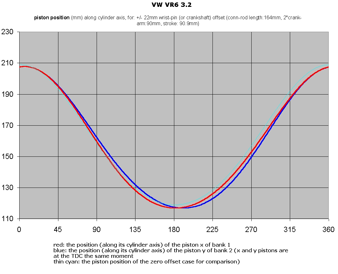
On the other hand, some work had already been done for engines having offset piston pins (or offset crankshaft).

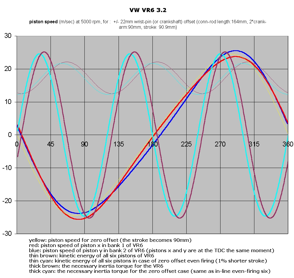
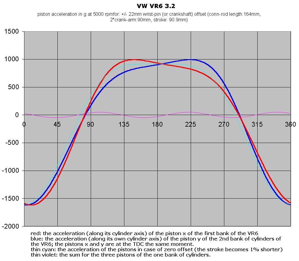
I made the necessary modifications of the xls file and here are the results:

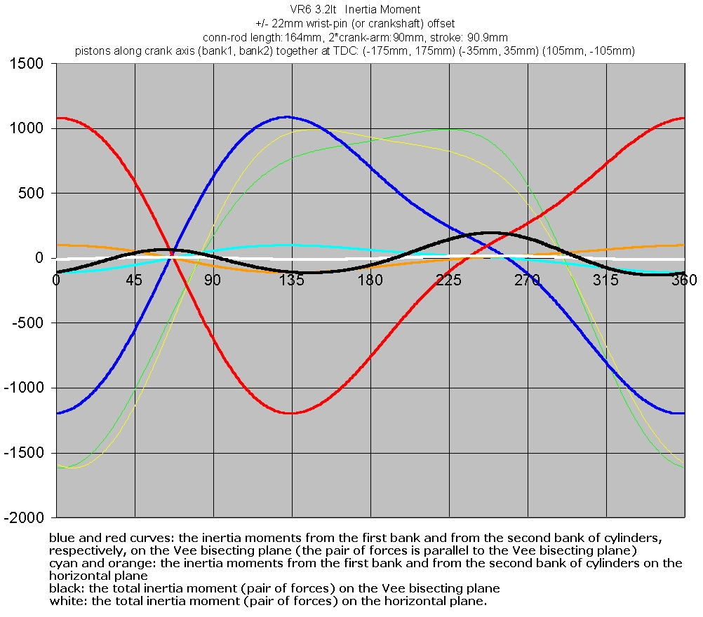
(the data used are from the PDF: Self Study Program 823603, VW 3.2 and 3.6 liter FSI Engine; I am not sure about the center to center length of the con-rod (some say 164mm, others say different), but having the xls file, you can put the correct data). The xls file is at VW VR6 xls

Posted Image

Posted Image

Posted Image

The inertia torque is substantially the same (amplitude, harmonics) with the inertia torque of the even firing six.

Looking at the piston travel curves, the rythm the piston of the one bank approaches to the TDC is different than the rythm the respective piston of the other bank approches to its own TDC. I.e. This engine is an "even" firing, however it comprises two sets of "different" cylinders (I suppose that, depending on the load and revs, the spark timing is different for the two banks of cylinders).

The inertia forces from the three pistons of the one bank are substantially balancing each other. I.e. the inertia forces are balanced.
What remains is the inertia moments, which, I think, are not so small. Does the VR6 have a 1st order balance shaft?

Thanks
Manolis Pattakos

#23 mariner

mariner
  • Member

  • 2,381 posts
  • Joined: January 07

Posted 19 August 2013 - 08:56

Or , of course, you could eliminate all the unbalanced forces in the first place ( if your name is Fred Lanchester)

http://media.carandd...-s-original.jpg

Remember each piston had two light connecting rods and one heavy one so even they were balanced.

It was of course bulky but faced with the materials he had it's one very elegant solution.

He was pretty smart at maths too!

#24 Magoo

Magoo
  • Member

  • 3,820 posts
  • Joined: October 10

Posted 19 August 2013 - 11:56

Or , of course, you could eliminate all the unbalanced forces in the first place ( if your name is Fred Lanchester)

http://media.carandd...-s-original.jpg

Remember each piston had two light connecting rods and one heavy one so even they were balanced.

It was of course bulky but faced with the materials he had it's one very elegant solution.

He was pretty smart at maths too!


Anytime you can work Lanchester into the discussion, it's worthwhile. :up:

#25 TDIMeister

TDIMeister
  • Member

  • 318 posts
  • Joined: January 06

Posted 19 August 2013 - 12:03

That's very interesting Manolis, I had done a spreadsheet just like yours for a discussion here: http://www.eng-tips.....cfm?qid=275803

The graphs are here (for the 2.8 VR6 with 15° bank angle and +/-12.5mm offset centrelines). But since this thread is about the Porsche flat-8, I will not contribute to the tangent simply by posting the links:
Displacement: http://bit.ly/aDqcPv
Velocity: http://bit.ly/bRyAmY
Acceleration: http://bit.ly/91Ri58

I had not developed the inertia torque calculation for the above until a later time; these were done back in July 2010.

#26 TDIMeister

TDIMeister
  • Member

  • 318 posts
  • Joined: January 06

Posted 19 August 2013 - 12:25

Or , of course, you could eliminate all the unbalanced forces in the first place ( if your name is Fred Lanchester)

http://media.carandd...-s-original.jpg

Remember each piston had two light connecting rods and one heavy one so even they were balanced.

It was of course bulky but faced with the materials he had it's one very elegant solution.

He was pretty smart at maths too!

This is in effect what Neander and Simplicity Motor Works are doing, among others. Maxsym had an interesting design also that did not require two crankshafts and two sets of counter-rotating weights. If memory services Manolis also has variations of mirrored rod mechanisms.

#27 manolis

manolis
  • Member

  • 935 posts
  • Joined: May 03

Posted 19 August 2013 - 14:31

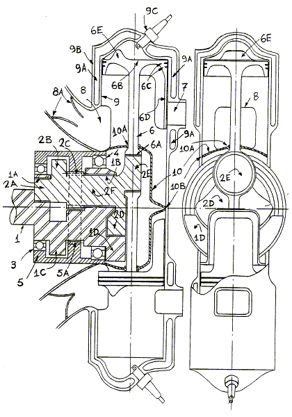
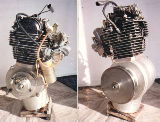
Talking for true-vibration-free arrangements, this one ( at the bottom of the http://www.pattakon....pattakonPPE.htm ) :

Posted Image

(above is the single sided version, below is the double-sided single cylinder prototype made and tested)

Posted Image

is a harmonic single cylinder which is perfectly balanced as regards all inertia loads: forces and torques and moments.

The prototype engine (353cc) can stand free on the floor (the basis is some 170mmx120mm) and rev from idling to 9000 rpm.

The Wankel rotary is not better; both are inertially perfect.

The Fred Lanchester design and the others mentioned suffer from strong 2nd order inertia torque (as the even firing fours): both pistons stop at the TDC and borh move with their maximum speed at the middle-stroke.

In comparison, in the harmonic the kinetic energy of the mechanism is constant during the crankshaft rotation.


If Feliks reads this: the Lanchester design and the harmonic design have "conventional" reciprocating pistons that do not thrust on the cylinder liner.


For divided load applications like the OPRE Portable Flyer (at http://www.pattakon....pattakonFly.htm ) :

Posted Image

the vibration free quality is even better than Wankel's rotary because the basis of the engine is not only rid of inertia vibrations of any kind and order, but it is also rid of power pulses vibrations of any order and kind.
If instead of two counter-rotating propellers, two counter-rotating electric generators are secured to the two crankshafts of the OPRE, a true vibration-free REM (Range Extenter Module) results.

Thanks
Manolis Pattakos

#28 rdyn

rdyn
  • New Member

  • 15 posts
  • Joined: June 11

Posted 20 August 2013 - 20:00

Found this 908 crankshaft picture (http://www.crankshaf...crankshafts.htm)

http://www.crankshaf...mages/pic/8.jpg


afaik 8 cylinder Continental / Lycoming are no boxer engines.


12 cylinder flat engines always (?) have 180°V configuration (shorter and stronger crankshaft, less main bearings). 12 cylinder V-engines are balanced (two inline 6 sharing crankpins), 60° firing order requires 60° or 180° V-angle.


#29 TDIMeister

TDIMeister
  • Member

  • 318 posts
  • Joined: January 06

Posted 20 August 2013 - 21:49

120° V12 can also yield even firing intervals.


#30 manolis

manolis
  • Member

  • 935 posts
  • Joined: May 03

Posted 21 August 2013 - 04:13

Found this 908 crankshaft picture (http://www.crankshaf...crankshafts.htm)
http://www.crankshaf...mages/pic/8.jpg
afaik 8 cylinder Continental / Lycoming are no boxer engines.


The plots (inertia force, inertia torque and inertia moment) with this crankshaft (crankpins at 0, 180, 180, 0, 90, 270, 270, 90) are the same with those of the arrangement no3 in the post 14.

Theoretically, this arrangement is equivalent (as regards the inertia vibrations) to the conventional eight cylinder Vee-90 (crossplane crankshaft).

In practice the rigidity of the crankshaft and of the block of this flat/boxer eight of Porsche 908 cannot be compared to the rigidity of the crankshaft and of the block of the conventional Vee-90 eight.

Thanks
Manolis Pattakos

#31 manolis

manolis
  • Member

  • 935 posts
  • Joined: May 03

Posted 21 August 2013 - 04:40

TDIMeister,
. . .
The inertia forces from the three pistons of the one bank are substantially balancing each other. I.e. the inertia forces are balanced.
What remains is the inertia moments, which, I think, are not so small. Does the VR6 have a 1st order balance shaft?
Thanks
Manolis Pattakos

Regarding the inertia moment of the VR6 of VW (post 22):

In the initial xls program they have been added a few columns wherein the inertia moment of the VR-6 is calculated (the new xls file is at http://www.pattakon....mpman/VR6_B.xls )

The resulting plot is:

VR6_d.jpg

Obviously the VR6 does not need additional balancing shafts.
Most of the inertia moment generated from the one bank of cylinders is counterbalanced by the inertia moment generated in the other bank of cylinders.
The arrangement of the crankpins makes the difference.

Think of the VR6 not as a modified Vee, but as a "compressed" inline six. The first and sixth pistons are at the TDC the same moment; the second and the fifth pistons are the the TDC the same moment; the third and the fourth pistons are at the TDC the same moment.

Thanks
Manolis Pattakos

Edited by manolis, 21 August 2013 - 04:42.


#32 rory57

rory57
  • Member

  • 98 posts
  • Joined: November 10

Posted 25 August 2013 - 19:46

Of course there were two British F1 flat eights......... in the BRM H16. Plenty of info on that engine out there. Google found me this:


 http://img90.imagesh...1/brmh16rq1.jpg


clearly showing each half to be a "180deg V8", pairs of cylinders firing together.


Still trying to find a pic. of the Lycoming IO720 flat eight aero engine.


Edited by rory57, 25 August 2013 - 20:10.


#33 rory57

rory57
  • Member

  • 98 posts
  • Joined: November 10

Posted 27 August 2013 - 12:08

For the record, the Lycoming aero-engine crankshaft can be seen here: http://www.enginehis...rankshaft_1.jpg

and it's firing order here: http://www.enginehis...FiringOrder.jpg


Obviously it is a true boxer engine, the plane of the centre four throws is at 90deg. to the plane of the two throws at each end. The bolt-on parts shown (2 of a possible 8) are torsional vibration dampers and not counterweights. Note the size of the front main bearing, there to support the propeller.


Have a look at http://www.youtube.c...h?v=yLLG2_ErvJs to see what happens when that propeller  support is not good enough. Listen carefully at around 30 seconds in and you will hear the engine whoop as it is liberated from the prop. :cry:


Thanks to Kim at http://www.enginehistory.org/ for finding the info. It's a great site, a man could spend a career in there.


#34 autouniondkw

autouniondkw
  • New Member

  • 5 posts
  • Joined: November 13

Posted 20 November 2013 - 19:09

Hi Guys.  Joining in on the forum after reading this whole thread completely.


Has anyone come to the conclusion on which crank or other configuration to use to make the flat-8 vibration free?


#35 indigoid

indigoid
  • Member

  • 384 posts
  • Joined: March 04

Posted 21 November 2013 - 02:06

Of course there were two British F1 flat eights......... in the BRM H16. Plenty of info on that engine out there. Google found me this:


 http://img90.imagesh...1/brmh16rq1.jpg


Beautiful solution to the problem of engine reliability. :rotfl:


#36 manolis

manolis
  • Member

  • 935 posts
  • Joined: May 03

Posted 21 November 2013 - 03:55

Hi Guys. Joining in on the forum after reading this whole thread completely.

Has anyone come to the conclusion on which crank or other configuration to use to make the flat-8 vibration free?


Hello autouniondkw.

The arrangement no. 3 in the post 14 of this thread is vibration free and even firing.

The crankpins are arranged at 0, 180, 90, 270, 270, 90, 180 and 0 crankshaft degrees as in the figure below:

Eight3.gif

It is actually a series of four two-cylinder even-firing boxers.

Also the 0, 180, 180, 0, 90, 270, 270 and 90 is vibration free and even firing.

Also the 0, 180, 90, 270, 180, 0, 270 and 90 is vibration-free and even firing.

I.e. you can swap the four two-cylinder even-firing boxers along the crankshaft axis keeping the vibration-free quality and the even-firing of the boxer eight.

You can easily check all these with the balance.exe DOS program in the Teaching section of the http://www.pattakon.com web site.

Thanks
Manolis Pattakos

#37 autouniondkw

autouniondkw
  • New Member

  • 5 posts
  • Joined: November 13

Posted 21 November 2013 - 05:45

Hi Manolis.


Thanks for the response!  Is there an advantage/disadvantage to the two options you have given?


Also I dont know the correct terminology, but does each have its own web bearing journals, or are two connecting rods shared for each journal in these setups?

(easiest to describe this like this:  bearing: rod: bearing: rod: bearing        OR       bearing: rod: rod: bearing: rod: rod: bearing)  ?


Sorry to sound uneducated, but is this considered a cross-plane crank?


Thanks again for the response.


#38 Greg Locock

Greg Locock
  • Member

  • 6,446 posts
  • Joined: March 03

Posted 21 November 2013 - 09:58

There are advantages to do with practicality and torsional vibrations, and possibly crank bearing loadings. There are also advantages with exhaust and intake manifold design.


Which is why engine design is so interesting. All of those can be considered, and analytical methods exist for them, but there is no one size fits all solution. A slightly simpler case I've worked on is the firing order for an i6. Toyota use a different firing order to us, so we built both, just to see. 


#39 indigoid

indigoid
  • Member

  • 384 posts
  • Joined: March 04

Posted 21 November 2013 - 12:49


Which is why engine design is so interesting. All of those can be considered, and analytical methods exist for them, but there is no one size fits all solution. A slightly simpler case I've worked on is the firing order for an i6. Toyota use a different firing order to us, so we built both, just to see. 


Actually it seems that Barra may be the oddball with its 163524 (yes?) order... Google seems to indicate that every other i6 I can think of is 153624 - BMW, Toyota, MB, Chrysler, GM, Holden, Jaguar, Nissan, VW, and older Ford Falcons


Advertisement

#40 Greg Locock

Greg Locock
  • Member

  • 6,446 posts
  • Joined: March 03

Posted 21 November 2013 - 19:00

153624 is what we had when I used to work on the falcon I6, I'm also talking about 94 era Landcruisers. Interesting that they've changed it for Barra. That'll cause some confusion.


#41 TDIMeister

TDIMeister
  • Member

  • 318 posts
  • Joined: January 06

Posted 21 November 2013 - 19:11

163524 in an I-6 could not possibly yield proper natural engine balance (if one assumes even 120° firing intervals) anyway that I can imagine it.


#42 autouniondkw

autouniondkw
  • New Member

  • 5 posts
  • Joined: November 13

Posted 21 November 2013 - 19:45

 0, 180, 90, 270, 270, 90, 180 and 0 


0, 180, 180, 0, 90, 270, 270 and 90


0, 180, 90, 270, 180, 0, 270 and 90


what are the firing orders for these engines?


#43 indigoid

indigoid
  • Member

  • 384 posts
  • Joined: March 04

Posted 21 November 2013 - 21:31

163524 in an I-6 could not possibly yield proper natural engine balance (if one assumes even 120° firing intervals) anyway that I can imagine it.


Well, it was an internet thing, and thus very possibly wrong - I was already suspicious given the wording of Greg's post and the overwhelming consensus from other manufacturers


I'm having trouble finding much info on the Toyota FZ family used in 1990s Landcruisers


#44 Greg Locock

Greg Locock
  • Member

  • 6,446 posts
  • Joined: March 03

Posted 21 November 2013 - 21:45

the bible gives the following alternatives for an I6 124653 142635 145632 153624. 


the first looks like bad news to me, as does the 3rd, as there will be a lot of charge robbing. The bunching end to end also tends to excite crank modes more easily. The third is probably my least favourite as the progressive 4 then 5 then 6 etc is especially bad.


#45 TDIMeister

TDIMeister
  • Member

  • 318 posts
  • Joined: January 06

Posted 21 November 2013 - 22:03

There's something beautiful, elegant and symmetric about 153624 I6s in so many respects, i.e. balancing, gas exchange, etc.  The only real problems are 3rd, 6th, 9th, ... order critical torsional modes. :)


Edit: Wasn't this thread about flat-eights? :)


Edited by TDIMeister, 21 November 2013 - 22:06.


#46 manolis

manolis
  • Member

  • 935 posts
  • Joined: May 03

Posted 22 November 2013 - 05:40

0, 180, 90, 270, 270, 90, 180 and 0

0, 180, 180, 0, 90, 270, 270 and 90

0, 180, 90, 270, 180, 0, 270 and 90

what are the firing orders for these engines?

Hello autouniondkw.

Let's take the first arrangement of crankpins of the boxer eight:

0, 180, 90, 270, 270, 90, 180 and 0

Here is the resulting "cylinder angles"

0, 0, 90, 90, 270, 270, 180 and 180

How? The second crankpin is for the first cylinder of the second bank of cylinders which is arranged at 180 degrees from the first bank of cylinders, so the crankpin at 180 degrees corresponds to a true angle of 180+180=360=0degrees.
From another viewpoint: when the piston of the first cylinder is at TDC, the piston of the second cylinder is at TDC, too.

For even firing, the possible "firing orders" result as:

1, 5, (2,6), (6,2), (3,7), (7,3), (4,8), (8,4)

That is, the second cylinder will always fire fifth (i.e. 360 crank degrees after the 1st cylinder).

Note: the numbering of the cylinders start from the one end of the crankshaft and proceeds progressively along the crankshaft.
The "firing order" is not the conventional firing order. The 5 in column 2 says that the second cylinder will fire 5th.


The third cylinder can fire either second (then the fourth cylinder will fire sixth) or sixth (and then the fourth cylinder will fire second). I.e. there are two cases for the pair of the 3rd and 4th cylinder.
So, until now, we have two different "firing orders":

1, 5, 2, 6 (??)

and

1, 5, 6, 2 (??).

The fifth cylinder can fire either third (then the sixth cylinder will fire seventh) or seventh (and then the sixth cylinder will fire third). I.e. there are two cases for the pair of the 5th and 6th cylinders. In combination with the previous, here are the possible "firing orders":

1, 5, 2, 6, 3, 7, (??)

1, 5, 6, 2, 3, 7, (??)

1, 5, 2, 6, 7, 3, (??)

1, 5, 6, 2, 7, 3, (??)

The seventh cylinder can fire either fourth (then the eighth cylinder will fire eight) or eighth (and then the eighth cylinder will fire fourth. I.e. there are two cases for the pair of the 7th and 8th cylinders. In combination with the previous, all the available "firing order" of the even firing boxer eight having crankpins at 0, 180, 90, 270, 270, 90, 180 and 0 are:

1, 5, 2, 6, 3, 7, 4, 8 (conventional firing order: 1, 3, 5, 7, 2, 4, 6, 8)

1, 5, 6, 2, 3, 7, 4, 8 (conventional firing order: 1, 4, 5, 7, 2, 3, 6, 8)

1, 5, 2, 6, 7, 3, 4, 8 (conventional firing order: 1, 3, 6, 7, 2, 4, 5, 8)

1, 5, 6, 2, 7, 3, 4, 8 (conventional firing order: 1, 4, 6, 7, 2, 3, 5, 8)

1, 5, 2, 6, 3, 7, 8, 4 (conventional firing order: 1, 3, 5, 8, 2, 4, 6, 7)

1, 5, 6, 2, 3, 7, 8, 4 (conventional firing order: 1, 4, 5, 8, 2, 3, 6, 7)

1, 5, 2, 6, 7, 3, 8, 4 (conventional firing order: 1, 3, 6, 8, 2, 4, 5, 7)

1, 5, 6, 2, 7, 3, 8, 4 (conventional firing order: 1, 4, 6, 8, 2, 3, 5, 7)


Take the first case:
1, 5, 2, 6, 3, 7, 4, 8
It corresponds to the conventional firing order: 1, 3, 5, 8, 7, 2, 4, 8. Similarly the rest.

You can apply the same reasoning to get the possible firing orders of the other two arrangements (the one with the crankpins at 0, 180, 180, 0, 90, 270, 270 and 90, the other with the crankpins at 0, 180, 90, 270, 180, 0, 270 and 90).

Having all the firing orders, you have to decide which is the best for your application (and there are several criteria to do so).


On the other hand, think that a Vee 90deg eight cylinder can be as vibration free as the above boxers, it can also be even firing, it has a substantially stronger crankshaft structure and its block is more lightweight and robust.
Is there any reasoning for going to the boxer arrangement?

Thanks
Manolis Pattakos

Edited by manolis, 22 November 2013 - 06:06.


#47 autouniondkw

autouniondkw
  • New Member

  • 5 posts
  • Joined: November 13

Posted 22 November 2013 - 08:23

I was looking to go with a different design then the standard v8.  The flat engines always intrigued me, lower center of gravity although a weight and packaging disadvantage.  I always thought the boxer engines would have a balance advantage over a v8, but I guess not.
 

I am planning to build a engine and after you talking me out of the flat-8, here are a couple other options that interested me:

1. Large displacement flat-4 ( 3.5l range, 108-110mm bore, with decent redline 7500-8000)

2. flat- 12  (7-8 liter displacement)

3. 120 degree v-12  (also 7-8 liter displacement)


What do you think about these?  I like the idea of the flat-4, due to simplicity and weight, but that large of displacement for only 4 cylinders may lead to some issues, one might be a low redline.


edit:

this might be worthy of its own thread or perhaps to private messaging.  thanks.


Edited by autouniondkw, 22 November 2013 - 08:23.


#48 manolis

manolis
  • Member

  • 935 posts
  • Joined: May 03

Posted 23 November 2013 - 03:52

I was looking to go with a different design then the standard v8. The flat engines always intrigued me, lower center of gravity although a weight and packaging disadvantage. I always thought the boxer engines would have a balance advantage over a v8, but I guess not.

I am planning to build a engine and after you talking me out of the flat-8, here are a couple other options that interested me:
1. Large displacement flat-4 ( 3.5l range, 108-110mm bore, with decent redline 7500-8000)
2. flat- 12 (7-8 liter displacement)
3. 120 degree v-12 (also 7-8 liter displacement)

What do you think about these? I like the idea of the flat-4, due to simplicity and weight, but that large of displacement for only 4 cylinders may lead to some issues, one might be a low redline.

edit:
this might be worthy of its own thread or perhaps to private messaging. thanks.


Autouniondkw,

About the 3.5l boxer four, with 110mm bore: the piston stroke should be 92mm. At 8000rpm it gives a mean piston speed of 24.5 m/sec. High but not forbidden. Honda S2000 has, at the redline, 25.2 m/sec mean piston speed (84mm stroke, 9000rpm).

The arrangements you are thinking of making already exist (big capacity flat boxer four, big flat 12, big 120 deg V12).

If you have the money and the time, it would be way more interesting to deal with more unconventional engines and new designs.

For instance:

Why not to built the first two-stroke engine with true four-stroke lubrication and true four-stroke scuffing resistance? Take a look at the PatMar engine at http://www.pattakon....takonPatMar.htm (or at the PatPortLess for high revving).
Do you want big capacities? The PatMar design fits, among others, to the giant (say 2500mm piston stroke) low-speed marine engines. Imagine the difference from the air-pollution viewpoint and from the running-cost (in short and long term) viewpoint
With "only" 400mm piston stroke and 90mm bore you can make a top fuel-efficient PatMar power generation set.
With "only" 250mm piston stroke and 100mm bore you can make a four in line, full balanced (as balanced as the boxer V-8 in this thread) PatMar truck engine.

Or why not to built a single cylinder compact and lightweight and perfectly balanced (i.e. perfectly vibration-free) and reliable engine like the OPRE tilting as presented at autosport forums at http://forums.autosp...-rotary-valves/

Or why not to built an engine having a variable compression ratio system like the HeadBlock VCR at http://www.pattakon....pattakonVCR.htm ?

Or why not to built a light weight and compact and fully balanced and high-revving single cylinder opposed-piston Diesel for motorcycles / small-medium size cars like the PatOP at http://www.pattakon....ttakonPatOP.htm ?

Thanks
Manolis Pattakos

#49 autouniondkw

autouniondkw
  • New Member

  • 5 posts
  • Joined: November 13

Posted 23 November 2013 - 18:01

I need the performance to be at the high point.  I plan on forced induction to get there.  800-1200hp.


You mention there is already a large displacement flat-4 engine.  Who has one in the 3.5l range?  I would imagine that they dont have good flowing cylinder heads then...


#50 indigoid

indigoid
  • Member

  • 384 posts
  • Joined: March 04

Posted 24 November 2013 - 02:48

I need the performance to be at the high point.  I plan on forced induction to get there.  800-1200hp.


You mention there is already a large displacement flat-4 engine.  Who has one in the 3.5l range?  I would imagine that they dont have good flowing cylinder heads then...


Lycoming and Rotax both sell flat-4 engines for aviation. Here's one of 3.8L ish displacement


https://en.wikipedia...Lycoming_IO-233


Probably wildly inappropriate for your application?


Subaru have 2.5L boxers. For their 3L range they went to six-cylinder boxers. Porsche did the same when their boxers started getting bigger. Maybe there's something in that. I am sure one of the folks here who actually knows stuff about engines could tell you why