Fondles,
The Thompson coupling is different.
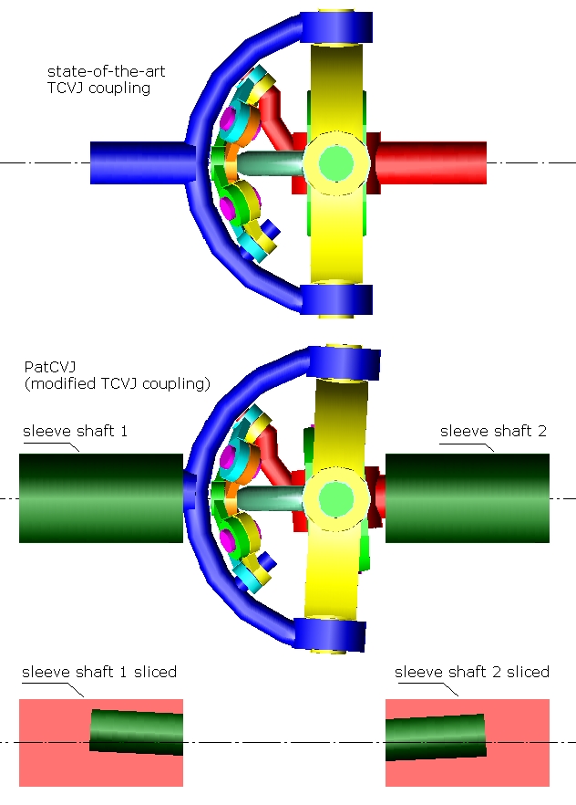
The Thomson coupling (TCVJ) is shown at top.
According the inventor and maker of the TCVJ coupling, a minimum angle of two degrees between the shafts is required, otherwise the parts of the TCVJ coupling rapidly wear.
The TCVJ is for small angles between the driving and driven shafts (some models are for 15 degrees, some other for no more than 10 degrees). Imagine putting in the middle of an already narrow range of angles another limitation not allowing angles from –2 to +2 degrees. What is left?
Under the TCVJ, in the figure above, it is a modification (we call it PatCVJ) that solves this problem of the TCVJ. The pivot axes A1 and A2 are oblique to the rotation axes of the respective shafts. The PatCVJ is already patented in the UK; in the US the patent has already been approved and is to be granted in a few weeks.
Both, the PatCVJ and the TCVJ comprise a main set of yokes and an auxiliary set of yokes / links.
The "main set of yokes" comprises:
a first yoke (the cyan cross at the center, in the animation above) pivotally mounted to a first shaft (the red shaft),
a second yoke (the yellow ring-cross) pivotally mounted to a second shaft (the blue shaft),
and a "control" yoke (the dark green fork) which is pivotally mounted to said first yoke and to said second yoke so that the three yokes of the "main set of yokes" pivot about a common axis.
The three "main yokes" make the hard work of transferring the torque load and the axial load from the one shaft to the other.
The "auxiliary set of yokes" comprises six articulated arc-shaped links (or yokes) that constitute a spherical pantograph mechanism (the two yellow links, the two cyan links, the green "rocker" link and the brown "rocker" link in the above animation). The one end of the pantograph pivots about an oblique pin of the first shaft, the other end of the pantograph pivots about an oblique pin of the second shaft. The center of the spherical pantograph keeps the "control" yoke at the right orientation so that the transmission ratio remains strictly at 1:1.
The PatDan Constant Velocity Joint is different.
It comprises three "main sets of yokes" like the abovementioned, and none "auxiliary set of yokes".
The three "control" yokes (the green, the yellow and the cyan crosses at the center of the animation above) are pivotally mounted to each other so that they pivot about a common axis.
The rest yokes are forks (the blue ones are pivotally mounted to the upper / brown shaft, the red ones are pivotally mounted to the lower / dark green shaft).
The forks are properly bend to allow wider angles of operation.
The torque load and the axial load split among all yokes.
The PatDan can take heavy axial loads.
So, the PatCVJ is similar to the TCVJ of the Australian Thompson Coupling, but the PatDan CVJ is quite different.
NotAPineapple:
The PatDAN shown in the stereoscopic animations fits to wide angles and to axial loads as is. But if you want to take heavy axial loads, crosses supported at both ends can substitute the red and blue yokes (or links), as in:
Can you, please, explain what you mean by: “Doesn't look like it can support axle plunge unless another sliding part is added”. Does a Rzeppa CV joint need "another sliding part to be added"?
Greg Locock:
Geometrically speaking, the PatDan is a very interesting and, at the same time, complicated problem. For instance, try to figure out the angle between the pivot axes and the respective shaft axes in order to achieve an operating angle range between, say, 0 and X degrees between the driving / driven shafts.
Thanks for mentioning the NTN.
At
http://www.ntn.co.jp...R75_en_P016.pdf (pdf of 2007) NTN explains the steps/modifications they did in order to increase the highest maximum operating angle of the Rzeppa CV joints of the automobile drive shafts to 54 degrees. With the PatDan we can have, at once, more than 60 degrees, with several times lower friction.
John Brundage:
What do you mean by radial torque? There is a torque passing from the one shaft to the other, there is also an axial load passing from the one shaft to the other. The limiting factor is the strength of the yokes / shafts involved and the static / dynamic loads the roller bearings can bear.
Thanks
Manolis Pattakos


