Jump to content


Photo
- - - - -

Sleeve Valves vs. Opposed Pistons


  • Please log in to reply
59 replies to this topic

#1 manolis

manolis
  • Member

  • 935 posts
  • Joined: May 03

Posted 30 August 2015 - 04:38

Hello.

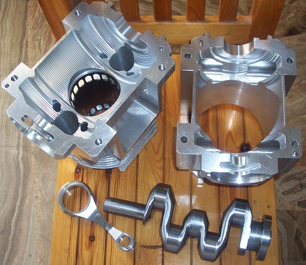
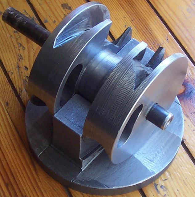
I was looking at this:

RR%20Crecy.gif

arrangement of Rolls-Royce Crecy 2-stroke as a solution for modern 2-strokes.

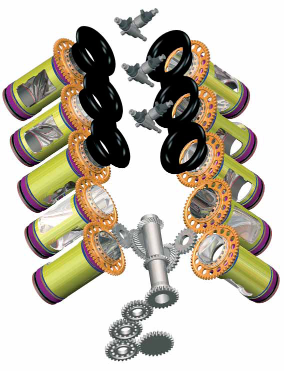
The sleeve valves of R-R Crecy move at double frequency than the sleeve valves of the Bristol Radials 4-strokes:

11BristolHercules734.jpg

While the angular oscillation of the Bristol sleeve valves about their cylinder axes offers a significant functional advantage (maximization of the valve-time-area), this is not the case for the Crecy 2-strokes sleeve valves wherein the angular oscillation just increases the inertia loads and the friction.

In both cases it is required a strange connection between the sleeve valve and its actuator.

In both cases (R-R Crecy and Bristol sleeve) the sleeve valve is supported asymmetrically causing flexing and increasing the friction.

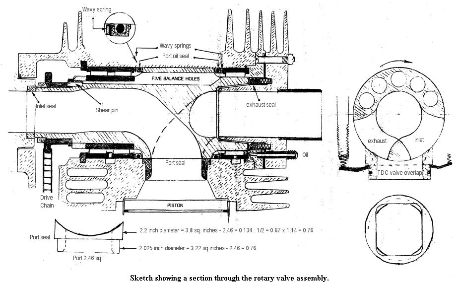
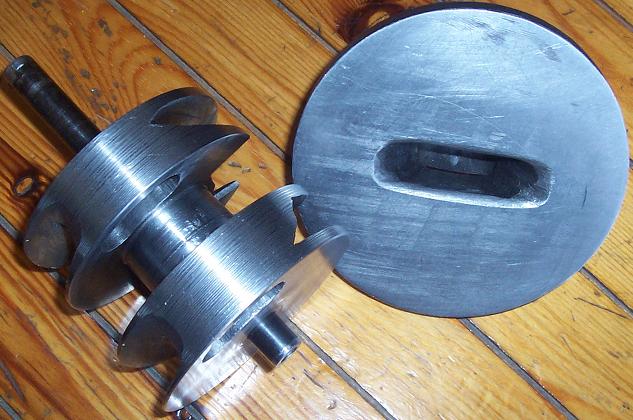
While the sealing of the combustion chamber of the Bristol sleeve valve engine is based on normal rings on the moving piston and on the stationary “piston”, in the Crecy R-R design the sealing of the top side of the combustion chamber is based on the tight fit of the sleeve valve top-end with the cylinder.


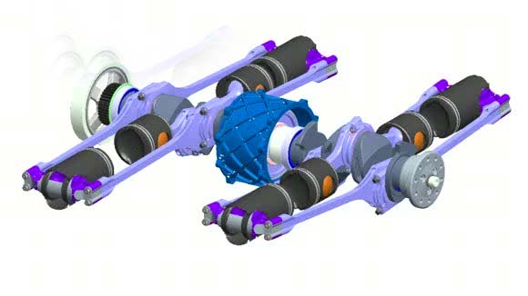
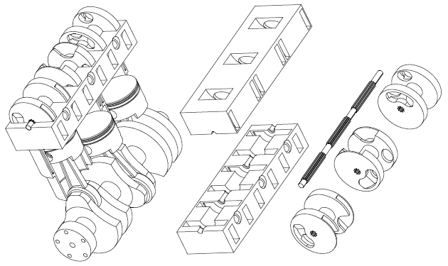
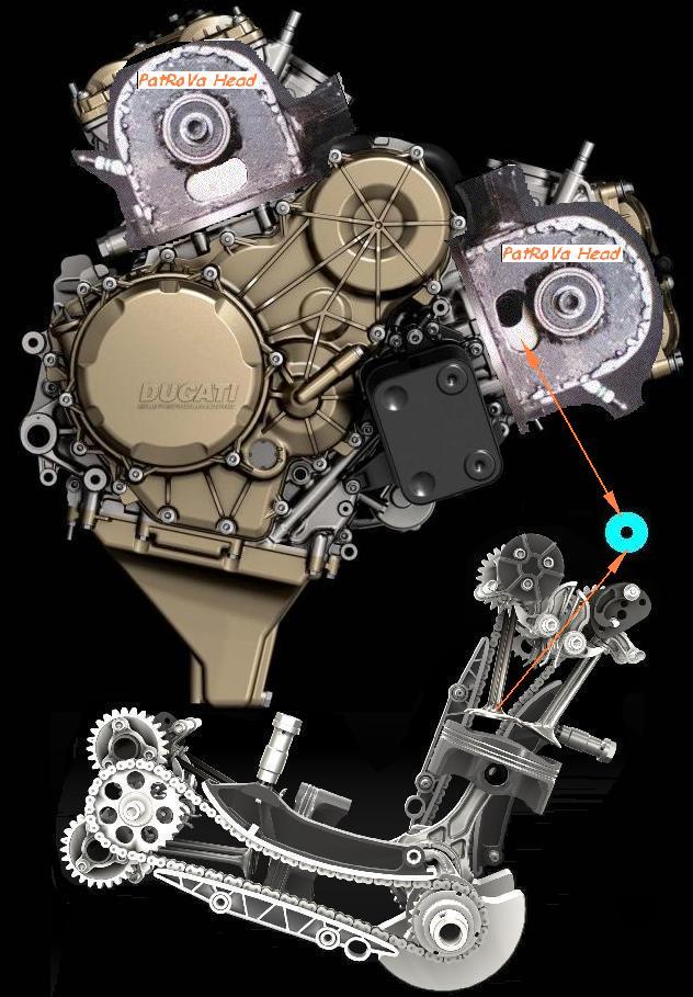
A better solution seems this:

Uniflow_sleeve.jpg

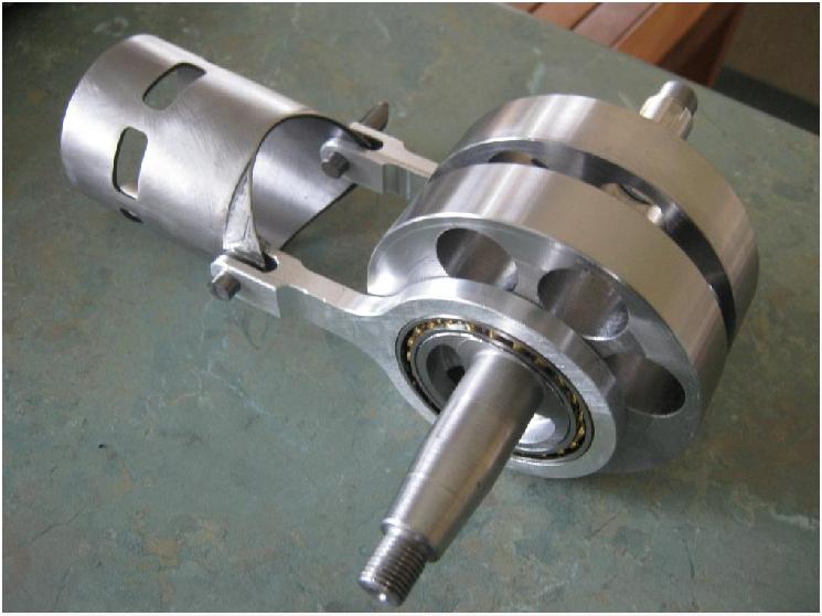
It is from a prototype sleeve valve two-stroke engine made by Uniflow (F1 Technical Forum).

As compared to Crecy sleeve valve, it is symmetrically supported by a pair of auxiliary side-connecting rods on two slim crankpins of small eccentricity, avoiding the angular oscillation about the cylinder axis.

A common problem with the R-R Crecy is the scavenging efficiency of the top part of the combustion chamber.
Even in the giant Marine two strokes (wherein the stroke is several times bigger than the bore) a core of residual hot gas remains along / around the axis of the cylinder (in this case the exhaust is at the opposite end of the cylinder and not in the middle of the cylinder).

A common problem is also the need for long stroke to bore ratios to put the transfer and exhaust ports away from each other (to avoid short circuit). The small distance of the transfer port from the top of the above sleeve valve shows the problem.


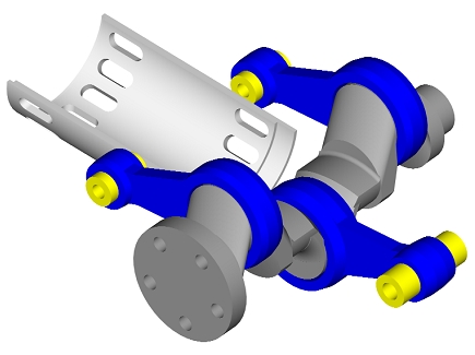
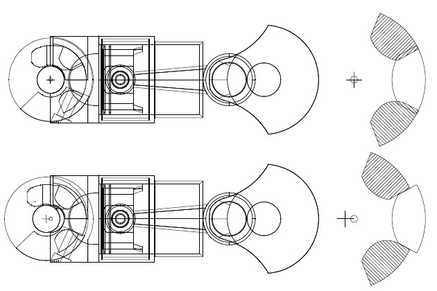
A better solution seems this design:

Sleeve3.gif

Sleeve3_STE.gif

At http://www.pattakon....eve/Sleeve3.gif amd http://www.pattakon....Sleeve3_STE.gif are the above animations at full size.

For windows users the following "exe" program may be interesting:http://www.pattakon....eve/Sleeve2.exe

(the second animation can be seen stereoscopically according the instructions at http://www.pattakon....Stereoscopy.htm )

Besides the simple actuation of the sleeve valve (Uniflow), it also offers the sealing quality of the Bristol sleeve valve design wherein a stationary piston at the top of the cylinder has piston rings sliding on the sleeve valve. No tight fit between the sleeve valve and the cylinder is required.

With the exhaust ports at the top of the cylinder, the scavenging is more efficient (fewer residual gas, lower cycle temperatures).

It seems a good solution.
But, as in the previous cases, it needs a long piston stroke.
A long piston stroke means heavier inertia loads, more friction, lower rev limit and less power.

A common disadvantage in all previous cases is the increase of the inertia loads and of the vibrations (the heavy sleeve valve reciprocates in synchronization with the piston; the first order inertia force of the reciprocating piston adds with the first order inertia force from the reciprocating sleeve valve). A single cylinder would vibrate a lot more than a conventional single cylinder 2-stroke (same piston, same connecting rod, same stroke, same rpm).


A better solution is to put in motion the immovable piston of the last arrangement.
This is what the Junkers-Doxford does:

US1679976.gif

Instead of using the side connecting rods for the sleeve valve, now the side connecting rods are used for the top piston.

The sleeve valve is eliminated together with the associated friction; the lubricant consumption reduces; the friction reduces (two pistons moving at half stroke).

The first order inertia forces are fully balanced.


A better solution is the OPOC (Opposed Piston, Opposed Cylinder engine) of Ecomotors (Bill Gates is one of their famous investors): two Junkers-Dosford share the same crankshaft for the sake of full balance:

OPOC_variable_capacity.jpg


A better solution is the PatPOC engine:

PatPOC_crosshead.gif

PatPOC_small2.gif

(more at http://www.pattakon....takonPatPOC.htm ; spot on the short crankshaft: the crankpins can be inside the cylinder footprint).


A better solution is also the PatOP engine:

patop4.jpg

PatOPbw.gif

PatOPpro2.jpg

(more at http://www.pattakon....ttakonPatOP.htm )

Among others it reduces the overall height of the engine, it takes the thrust loads on surfaces rid of ports, it has “four-stroke-like” lubrication, it has built-in piston-type scavenging pump etc.
The “pulling rod” architecture of the PatOP increases substantially the piston dwell around the combustion dead center (think what this means for a high revving Diesel)

Worth to mention that the main bearings of the crankshaft of all abovementioned Opposed Piston engines can run unloaded (think why); theoretically you can hold by your hands the crankshaft at operation.


Thoughts?
Objections?

Thanks
Manolis Pattakos

Edited by manolis, 30 August 2015 - 04:59.


Advertisement

#2 Wuzak

Wuzak
  • Member

  • 8,501 posts
  • Joined: September 00

Posted 31 August 2015 - 02:22

I believe the oscillating motion in the sleeve valves of the Bristol and Crecy systems was also to aid lubrication.


The Crecy was designed to be highly supercharged, the supercharger providing the scavenging for the cylinders. I believe there was a large percentage of the supercharged air that was pumped straight through the cylinders and out the exhaust. Maybe as high as 20%?


Doing without the sleeves must be better for reducing friction, however.


#3 manolis

manolis
  • Member

  • 935 posts
  • Joined: May 03

Posted 01 September 2015 - 02:54

Hello Wuzak.

You write:
“I believe the oscillating motion in the sleeve valves of the Bristol and Crecy systems was also to aid lubrication.”

The lubrication of a conventional piston needs not angular oscillation about the cylinder axis.
A sleeve valve is like an auxiliary piston reciprocating at a shorter stroke.
The angular oscillation of the Bristol 4-stroke sleeve valve is functional.
But the angular oscillation of the 2-stroke R-R Crecy sleeve valve seems like a side effect of the selected actuation mechanism.


You also write:
“The Crecy was designed to be highly supercharged, the supercharger providing the scavenging for the cylinders. I believe there was a large percentage of the supercharged air that was pumped straight through the cylinders and out the exhaust. Maybe as high as 20%?”

I suppose it was also a direct injection engine.
At partial load the recycling of (hot) “air pumped straight through the cylinder” seems reasonable (Honda Exp-2).
But at full load it is a problem.

With or without supercharging, the scavenging cannot be efficient (the stroke should be longer, the exhaust ports should be located at the top of the cylinder).
Even in the giant marine 2-strokes (wherein the stroke is several times the bore, the exhaust valve is disposed at the top of the cylinder and the transfer ports are disposed at the bottom of the cylinder) there are issues with the residual gas.

Thanks
Manolis Pattakos

#4 bigleagueslider

bigleagueslider
  • Member

  • 1,235 posts
  • Joined: March 11

Posted 01 September 2015 - 05:26

While I enjoy looking at the recip engine concepts you come up with, there are many practical reasons sleeve valve engine designs (both two-stroke and four-stroke) were abandoned in favor of conventional poppet valve designs. It mostly had to do with cost, oil consumption and durability. In fact, poppet valve four-stroke recip engines have now displaced two-strokes in most applications.


Every engine designer knows about sleeve valves. And if they worked as well as many people claim, there would be production engines using them right now. But as any serious engineer involved in the design of production engines understands, there are serious issues with sleeve valves that make them unsuitable for commercial use.


As for the R-R Crecy, it was a test engine design that was only operated for a limited amount of time on a dyno. It was not pursued because the cost of getting it into production could not be justified. There were turbojet engines in development that offered better performance for high speed aircraft, and there were existing recip engines that were acceptable for other aircraft applications that did not allow the development cost/risk of the Crecy.


#5 gruntguru

gruntguru
  • Member

  • 7,642 posts
  • Joined: January 09

Posted 01 September 2015 - 10:07

BLS:

None of Manolis designs above is sleeve valve.


Manolis.

Wuzak is correct about lubrication and orbiting sleeves. I recall Ricardo's original publications on the concept noted reduced piston wear - probably due to the fact that the piston-sleeve interface is never stationary, with rotation of the sleeve occurring at TDC and BDC.


#6 manolis

manolis
  • Member

  • 935 posts
  • Joined: May 03

Posted 01 September 2015 - 14:38

Hello Gruntguru and thanks.

You write:
“Wuzak is correct about lubrication and orbiting sleeves. I recall Ricardo's original publications on the concept noted reduced piston wear - probably due to the fact that the piston-sleeve interface is never stationary, with rotation of the sleeve occurring at TDC and BDC.”

In practice the 4-stroke Bristol Hercules and Centaurus sleeve-valve engines proved more than reliable (3,000 hours TBO).

Worth mentioning: Taylor, on the other hand, accuses the Wankel Rotary for “high velocity of the seal during the high pressure portion of the cycle, in contrast to the piston rings whose velocity is near zero at maximum cylinder pressure”


A couple of days ago I wrote to Uniflow / Flettner (he is the guy who makes the sleeve valve prototype 2-stroke) at the Kiwibiker forum ( http://www.kiwibiker...-tuner/page1284 )

"If all this trouble (new cylinder, sleeve valve, auxiliary connecting rods, new crankshaft etc) is in order to put exhaust ports at the top (or more correctly at the middle) of the cylinder of a 2-stroke, why not to use an exhaust PatRoVa rotary valve?"

PatRoVa_2Stroke.gif

Thoughts?
Objections?

Thanks
Manolis Pattakos

Edited by manolis, 01 September 2015 - 14:40.


#7 bigleagueslider

bigleagueslider
  • Member

  • 1,235 posts
  • Joined: March 11

Posted 08 September 2015 - 02:46

BLS:

None of Manolis designs above is sleeve valve.


Not even this one: http://www.pattakon....eve/Sleeve3.gif


#8 gruntguru

gruntguru
  • Member

  • 7,642 posts
  • Joined: January 09

Posted 08 September 2015 - 05:15

My bad - sorry. :)


#9 manolis

manolis
  • Member

  • 935 posts
  • Joined: May 03

Posted 09 September 2015 - 17:03

Hello Bigleagueslider.

The animations and the “exe” program were made to see, and show, how a sleeve valve 2-stroke could operate.

The sleeve valve 2-strokes have several disadvantages as compared to the Opposed Piston 2-strokes.
Do you see any advantages?


Regarding the PatRoVa Rotary Valve (my last post) and its substantially different architecture as compared with the state-of-the-art Coates rotary valves:

Suppose that a COATES intake spherical rotary valve seals a chamber port of 20cm2 port-area substituting the two 36mm diameter intake poppet valves of a conventional 500cc cylinder, suppose also that a COATES exhaust spherical rotary valve seals a chamber port having 20cm2 port-area substituting the two exhaust poppet valves of the 500cc cylinder.

5327688.jpg?1305294237

A 100bar pressure during the combustion (turbocharged engines operating at substantially higher than 100 bar maximum pressure are quite common) causes an upwards force of 2 tons (20cm2*100Kp/cm2) on the intake spherical rotary valve and another upwards force of 2 tons on the exhaust rotary valve.

If the same shaft supports both COATES spherical rotary valves, the total force loading the bearings of the rotary valve shaft, is 4 tons.


In the case of the PatRoVa rotary valve, two chamber-ports, each having only 10cm2 port-area, offer the same flow capacity.

Notice: the architecture of the PatRoVa rotary valve allows the same chamber-ports to be used for both, the intake and the exhaust processes; in the COATES spherical rotary valve architecture there are chamber ports dedicated to the intake process, and others (necessarily hot) chamber-ports dedicated to the exhaust.

A 100bar pressure during the combustion causes a side force of 1 ton (100Kp/cm2 * 10cm2) on the one front and an equal and opposite force of 1 ton on the oppositely arranged front of the PatRoVa rotary valve.
The two fronts are firmly secured to each other by a robust shaft / hub.
In total, the bearings supporting the PatRoVa rotary valve can run completely unloaded.


From a practical viewpoint:

Leaving free (i.e. without support bearings) the PatRoVa rotary valve on the cylinder head to seat in place and seal, by its oppositely arranged fronts, the two side chamber-ports,

PatRoVa_photo3.jpg

and applying a high pressure (like 100bar) in the combustion chamber,
the PatRoVa rotary valve has no tendency to move upwards, or downwards, or to the side.

In comparison, a force of a few tons is required to keep in place the COATES spherical rotary valve when the same 100bar pressure is in the combustion chamber; the extreme upwards force loads its bearings and causes, among others, the flexing / deformation of the spherical valve, of the shaft of the rotary valve and of the cylinder head wherein the shaft is supported.


Things are, more-or-less, the same if instead of the Coates spherical rotary valves, the Bishop – Cross rotary valves were used for the comparison.

Thoughts?

Objections?

Thanks
Manolis Pattakos

#10 bigleagueslider

bigleagueslider
  • Member

  • 1,235 posts
  • Joined: March 11

Posted 10 September 2015 - 04:45

The rotary valve used on the N/A 4T Ilmor race engine seemed to work quite well. While it was prevented from being used in F1 racing by regulations, that did not prevent it from being comercialized. So why have we not seen this rotary valve design used on a production engine?


#11 gruntguru

gruntguru
  • Member

  • 7,642 posts
  • Joined: January 09

Posted 11 September 2015 - 02:49

Same reason many superior designs never managed to oust the status quo.


In the case of the BRV it is possible to be more specific. Its main advantage over poppet valve designs is power output. Auto makers already have no problem producing road vehicles with unacceptably high power output - no need to invest in new technology to make more power.


Edited by gruntguru, 11 September 2015 - 02:52.


#12 manolis

manolis
  • Member

  • 935 posts
  • Joined: May 03

Posted 11 September 2015 - 07:47

Hello Bigleagueslider.

You write:
“The rotary valve used on the N/A 4T Ilmor race engine seemed to work quite well. While it was prevented from being used in F1 racing by regulations, that did not prevent it from being comercialized. So why have we not seen this rotary valve design used on a production engine?”


Here is the Bishop rotary valve (Ilmor racing):

bishop%20rotary%20valve.jpg

image_5.png

It is a thin-walled cylinder with a diagonal separator in the middle, red hot at one side (exhaust), cold at the other side (inlet) with two needle roller bearings disposed necessarily at its ends (to make space for the two long rotary valve ports) and tons of force pushing it away from the combustion chamber during the combustion.

The diagonal separation introduces a significant asymmetry: the temperature of the rotary valve varies substantially not only along, but also around the rotary valve axis. Think the result of the thermal expansion on the shape of the rotary valve.

However,
for extreme revs and heavy/full load (as in Formula1), Bishop rotary valve has advantages due to its high flow capacity.

For civil / commercial applications (cars, motorcycles etc), there are significant issues to be addressed, like the emissions (leakage of unburned mixture to the exhaust), long term reliability, fuel efficiency etc.

There are others, more practical, issues, like the complexity of a multicylinder arrangements and the central location of the spark plugs.
Compare a Bishop rotary valve multicylinder:

bishop_rotary_valve.jpg

with the PatRoVa rotary valve multicylinder:

PatRoVa_I3.jpg


The differences of the Bishop rotary valve from the original Cross rotary valve:

cross%20section.jpg

are not significant, if any.

Ralph Watson manufactured and tested for long Cross rotary valves of his own design:

Rotary_Valve_Ralf_Watson_0.jpg

Rotary_Valve_Ralf_Watson_1.jpg

Rotary_Valve_Ralf_Watson_2.jpg

Rotary_Valve_Ralf_Watson_3.jpg

Do read his article at http://ralphwatson.s...net/rotary.html


Is the PatRoVa rotary valve different?

PatRoVa2.gif

Quote from http://www.pattakon....akonPatRoVa.htm :


Leakage internally recycled

Any gas leakage from the combustion chamber during the compression / combustion is recycled: it returns into the cylinder at the next suction cycle.
This built-in "recycling" of the unburned gas leakage is even more important at the warming-up period wherein the clearance between the valve fronts and the chamber ports is not yet minimized.


Combustion chamber

The combustion chamber is compact. The piston crown is flat without pockets.
The combustion chamber is rid of hot spots (like, for instance, the hot exhaust poppet valves of the conventional engines, or like the hot chamber ports of the state-of-the-art exhaust rotary valves). Every point of the combustion chamber is equally related with the intake and with the exhaust. On this reasoning the compression ratio can further increase.
There is space for centrally located spark plug and/or injector.
No need for lubricant in the cylinder head; small (because the loads they bear are small) sealed roller bearings is all it takes for the support of the rotary valve. With the cylinder head running "dry", the lube specific consumption and the emissions decrease, while the lubricant degradation slows down.


Sealing

For the sealing . . . only the one of the three dimensions is significant: that one along the rotation axis of the rotary valve. . . The sealing is tolerant to deformations of the cylinder head because, as before, only the one of the three dimensions really matters; significant deformations of the chamber along the other two dimensions do not affect the sealing.


Multicylinder arrangements

A splined shaft drives all the rotary valves of a line (or bank) of cylinders.
At a thermal expansion (or contraction) each rotary valve slides slightly along the splined shaft and continues its friction-free / wear-free cooperation with the respective ports.
Instead of dealing with the expansion of a, say, 400mm long piece (case with all rotary valves of a bank of cylinders secured on a shaft), with the splined shaft the expansion concerns only the distance between the two disks of each rotary valve, i.e. 10 to 25mm.


Thanks
Manolis Pattakos

Edited by manolis, 11 September 2015 - 09:00.


#13 Kelpiecross

Kelpiecross
  • Member

  • 1,730 posts
  • Joined: October 10

Posted 11 September 2015 - 13:58


Very interesting stuff Manny.

#14 Peter0Scandlyn

Peter0Scandlyn
  • Member

  • 727 posts
  • Joined: September 14

Posted 12 September 2015 - 05:11

Fascinating stuff. Great to see R Watson's name mentioned too.


#15 manolis

manolis
  • Member

  • 935 posts
  • Joined: May 03

Posted 10 October 2015 - 04:28

In the post #6 I wrote:

“Hello Gruntguru and thanks.

You write:
“Wuzak is correct about lubrication and orbiting sleeves. I recall Ricardo's original publications on the concept noted reduced piston wear - probably due to the fact that the piston-sleeve interface is never stationary, with rotation of the sleeve occurring at TDC and BDC.”

In practice the 4-stroke Bristol Hercules and Centaurus sleeve-valve engines proved more than reliable (3,000 hours TBO).

Worth mentioning: Taylor, on the other hand, accuses the Wankel Rotary for “high velocity of the seal during the high pressure portion of the cycle, in contrast to the piston rings whose velocity is near zero at maximum cylinder pressure””


It seems that both, Ricardo and Taylor, are correct.

In the sleeve valve engines the “piston-sleeve valve interface is never stationary”. During the combustion this is bad as regards friction loss and good as regards the reliability.

In comparison, in the conventional engine the more-or-less stationary piston during combustion avoids spending mechanical energy to friction (which equals to the friction force times the distance the friction force travels); the problem is that the stationary piston rings, which are heavily pressed onto the top end of the cylinder liner by the high pressure, cannot help contacting the cylinder liner (metal to metal contact, scuffing). At stationary conditions the oil film is easy to break.

So, more friction doesn’t necessarily mean a worse reliability.
The reliability is defined but the weakest / most vulnerable “point” of the engine.

It is like in the roller bearings (at thread http://forums.autosp...lling-bearings/ ) : the appropriate preloading increases the reliability in expense of more friction and of lower maximum speeds.

Thanks
Manolis Pattakos

#16 fredric21

fredric21
  • New Member

  • 13 posts
  • Joined: October 15

Posted 14 October 2015 - 15:07

Kindly watch this space for a combination of non-ported sleeve valve and opposed piston engine currently under development by myself.  I will make no claims for the design, other than the fact that it is very novel and unorthodox!   When we have test results available only then will I divulge things a little further.  We are still in the patenting process, so I cannot divulge any details for that reason.


#17 Lee Nicolle

Lee Nicolle
  • Member

  • 11,061 posts
  • Joined: July 08

Posted 14 October 2015 - 22:10

For me this is why. Far too heavy and old fashioned for modern vehicles.

Sleeve engines make no sense,, only a Pom could envisage such complicated monsters. And even then maybe [just] ok for large aircraft but not for production vehicles.

Rotary valve has potential. There has been several conversions done decades past that made for the time decent power. Though sealing and durability were [and still are] a problem.

Look on the early Holden thread on TNF for pics of the Dunstan rotary valve head for a grey Holden engine. Of which about 30 were made and marketed by a local machine shop. In the 60s!


#18 PJGD

PJGD
  • Member

  • 143 posts
  • Joined: April 04

Posted 15 October 2015 - 00:57

fredric21; I assume that you are going to reveal a design that is based on, or is similar to, the Elsbett 4SOPE.

If so, I look forward to seeing your design.


PJGD


#19 Wuzak

Wuzak
  • Member

  • 8,501 posts
  • Joined: September 00

Posted 15 October 2015 - 10:43

For me this is why. Far too heavy and old fashioned for modern vehicles.

Sleeve engines make no sense,, only a Pom could envisage such complicated monsters. And even then maybe [just] ok for large aircraft but not for production vehicles.

Rotary valve has potential. There has been several conversions done decades past that made for the time decent power. Though sealing and durability were [and still are] a problem.

Look on the early Holden thread on TNF for pics of the Dunstan rotary valve head for a grey Holden engine. Of which about 30 were made and marketed by a local machine shop. In the 60s!


The Knight sleeve valve design was invented in 1903. It had two sleeves per cylinder, one running inside the other. Knight was American.


The single sleeve Burt-McCollum, which is the more familiar as it was used by Bristol, Rolls-Royce, Napier and Pratt & Whitney, was invented in 1909.


In both cases you could argue that the poppet valve was far from a mature design at that point.


Ricardo proposed the use of sleeve valves for aero engines because the low quality fuel at the time severely limited compression ratios, reducing the power attainable. His research indicated that single sleeve valve motors could take as much as 1 extra point in compression ratio - quit a substantial leap at that time.


He also suggested that the aero engine needed to be compression ignition, also because of low fuel quality.


But at around that time TEL was stating to be added to fuels, and fuel quality improved rapidly, not the least during WW2, lessening the advantage for sleeve valved engines.


Conceptually I don't think the sleeve valve is overly complicated. The execution can be, however - the Bristol sleeve valves look complicated because they need n crank and gear train to drive each sleeve.


Advertisement

#20 fredric21

fredric21
  • New Member

  • 13 posts
  • Joined: October 15

Posted 15 October 2015 - 12:35

I believe the oscillating motion in the sleeve valves of the Bristol and Crecy systems was also to aid lubrication.


The Crecy was designed to be highly supercharged, the supercharger providing the scavenging for the cylinders. I believe there was a large percentage of the supercharged air that was pumped straight through the cylinders and out the exhaust. Maybe as high as 20%?


Doing without the sleeves must be better for reducing friction, however.

Angular oscillation of the sleeve during its reciprocal motion is undesirable due to the need to bed in the rings to match the bore of the sleeve precisely. Failure to bed the rings to the sleeve in this manner results in increased wear and poor gas sealing which will always produce more blowby into the crankcase. Sleeve lubrication was never a problem and was solved very early on in development.  It was piston cooling that was the main problem and that resulted in piston to sleeve seizures, rather than sleeve to housing seizures.


#21 fredric21

fredric21
  • New Member

  • 13 posts
  • Joined: October 15

Posted 15 October 2015 - 12:47

fredric21; I assume that you are going to reveal a design that is based on, or is similar to, the Elsbett 4SOPE.

If so, I look forward to seeing your design.


PJGD

The Elsbett system is well hyped up for sure!!!  I make no claims until I can produce the data from thorough bench testing.


#22 fredric21

fredric21
  • New Member

  • 13 posts
  • Joined: October 15

Posted 15 October 2015 - 12:54

For me this is why. Far too heavy and old fashioned for modern vehicles.

Sleeve engines make no sense,, only a Pom could envisage such complicated monsters. And even then maybe [just] ok for large aircraft but not for production vehicles.

Rotary valve has potential. There has been several conversions done decades past that made for the time decent power. Though sealing and durability were [and still are] a problem.

Look on the early Holden thread on TNF for pics of the Dunstan rotary valve head for a grey Holden engine. Of which about 30 were made and marketed by a local machine shop. In the 60s!

Rotary valves are notoriously difficult to seal effectively against gas pressure.  I attempted to run a design utilising pistons located within a large rotary valve housing and could not get a seal despite generating huge amounts of friction.


#23 PJGD

PJGD
  • Member

  • 143 posts
  • Joined: April 04

Posted 16 October 2015 - 00:27

Ricardo proposed the use of sleeve valves for aero engines because the low quality fuel at the time severely limited compression ratios, reducing the power attainable. His research indicated that single sleeve valve motors could take as much as 1 extra point in compression ratio - quit a substantial leap at that time.


He also suggested that the aero engine needed to be compression ignition, also because of low fuel quality.


But at around that time TEL was stating to be added to fuels, and fuel quality improved rapidly, not the least during WW2, lessening the advantage for sleeve valved engines.


Writing in 1935, Ricardo had this to say on the topic: http://www.theengine...ctober-1935.pdf


I believe that it was also found that the mono sleeve valve was less susceptible to malfunction due to lead deposits with the high TEL dosage rates.


PJGD


Edited by PJGD, 16 October 2015 - 00:32.


#24 manolis

manolis
  • Member

  • 935 posts
  • Joined: May 03

Posted 16 October 2015 - 06:31

Hello Fredric21

You write:
"Rotary valves are notoriously difficult to seal effectively against gas pressure. I attempted to run a design utilising pistons located within a large rotary valve housing and could not get a seal despite generating huge amounts of friction."


Quote from http://www.pattakon....akonPatRoVa.htm :

"Load on bearings and shafts as compared to the state-of-the-art

In the following drawing, at right:
an intake spherical rotary valve seals a chamber-port of 20cm2 port-area (it substitutes two 36mm diameter intake poppet valves of a conventional 500cc cylinder),
an exhaust spherical rotary valve seals another chamber-port of 20cm2 port-area (it substitutes two exhaust poppet valves of the 500cc cylinder).
A 100bar pressure during the combustion (turbocharged engines operating at substantially higher than 100 bar maximum pressure are quite common) causes an "upwards" force of 2 tons (20cm2*100Kp/cm2) on the intake spherical rotary valve and another "upwards" force of 2 tons on the exhaust rotary valve.
If the same shaft supports both spherical valves, the total force loading the bearings of the rotary valve shaft is 4 tons.

In the case of the PatRoVa rotary valve, at left, two chamber-ports, each having only 10cm2 port-area, offer the same flow capacity

PatRoVa_comp.gif

The architecture of the PatRoVa rotary valve allows the same chamber-ports to be used for both, the intake and the exhaust processes; in the spherical rotary valve architecture there are chamber ports dedicated to the intake process, and others (necessarily hot) chamber-ports dedicated to the exhaust.

A 100bar pressure during the combustion causes a side force of 1 ton (100Kp/cm2 * 10cm2) on the one front and an equal and opposite force of 1 ton on the oppositely arranged front of the PatRoVa rotary valve.
The two fronts are firmly secured to each other by a robust shaft / hub.
In total, the bearings supporting the PatRoVa rotary valve can run completely unloaded.

From a practical viewpoint:
Leaving free (i.e. without support bearings) the PatRoVa rotary valve on the cylinder head to seat in place and seal, by its oppositely arranged fronts, the two side chamber-ports, and applying a high pressure (like 100bar) in the combustion chamber, the PatRoVa rotary valve has no tendency to move upwards, or downwards, or to the side.
In comparison, a force of a few tons is required to keep in place a state-of-the-art rotary valve when the same 100bar pressure is in the combustion chamber; the extreme upwards force loads its bearings and causes, among others, the flexing / deformation of the spherical valve, of the shaft of the rotary valve and of the cylinder head wherein the shaft is supported."

End of quote.


There are several and significant / fundamental differences between the PatRoVa and the state-of-the-art spherical and Cross-like rotary valves.

Unless 4tons vs zero (upwards load) is not a fundamental difference.

Spot on the size of the required rolling bearings.


Rid of seals,
with humble construction accuracy,
with less than low friction,
and with manual "cranking",
the second PatRoVa prototype "writes" 12bar (175 psi) pressure at the end of compression.

The same PatRoVa "rotary valve / cylinder head" assembly has been tested rotating for several minutes at 11,000rpm (it corresponds to 22,000rpm of the engine), without a piston in the cylinder.

Its size and ports are for some 400cc cylinders.


So, please take another look.

Thanks
Manolis Pattakos

#25 fredric21

fredric21
  • New Member

  • 13 posts
  • Joined: October 15

Posted 16 October 2015 - 08:44

Hello Fredric21

You write:
"Rotary valves are notoriously difficult to seal effectively against gas pressure. I attempted to run a design utilising pistons located within a large rotary valve housing and could not get a seal despite generating huge amounts of friction."


Quote from http://www.pattakon....akonPatRoVa.htm :

"Load on bearings and shafts as compared to the state-of-the-art

In the following drawing, at right:
an intake spherical rotary valve seals a chamber-port of 20cm2 port-area (it substitutes two 36mm diameter intake poppet valves of a conventional 500cc cylinder),
an exhaust spherical rotary valve seals another chamber-port of 20cm2 port-area (it substitutes two exhaust poppet valves of the 500cc cylinder).
A 100bar pressure during the combustion (turbocharged engines operating at substantially higher than 100 bar maximum pressure are quite common) causes an "upwards" force of 2 tons (20cm2*100Kp/cm2) on the intake spherical rotary valve and another "upwards" force of 2 tons on the exhaust rotary valve.
If the same shaft supports both spherical valves, the total force loading the bearings of the rotary valve shaft is 4 tons.

In the case of the PatRoVa rotary valve, at left, two chamber-ports, each having only 10cm2 port-area, offer the same flow capacity

PatRoVa_comp.gif

The architecture of the PatRoVa rotary valve allows the same chamber-ports to be used for both, the intake and the exhaust processes; in the spherical rotary valve architecture there are chamber ports dedicated to the intake process, and others (necessarily hot) chamber-ports dedicated to the exhaust.

A 100bar pressure during the combustion causes a side force of 1 ton (100Kp/cm2 * 10cm2) on the one front and an equal and opposite force of 1 ton on the oppositely arranged front of the PatRoVa rotary valve.
The two fronts are firmly secured to each other by a robust shaft / hub.
In total, the bearings supporting the PatRoVa rotary valve can run completely unloaded.

From a practical viewpoint:
Leaving free (i.e. without support bearings) the PatRoVa rotary valve on the cylinder head to seat in place and seal, by its oppositely arranged fronts, the two side chamber-ports, and applying a high pressure (like 100bar) in the combustion chamber, the PatRoVa rotary valve has no tendency to move upwards, or downwards, or to the side.
In comparison, a force of a few tons is required to keep in place a state-of-the-art rotary valve when the same 100bar pressure is in the combustion chamber; the extreme upwards force loads its bearings and causes, among others, the flexing / deformation of the spherical valve, of the shaft of the rotary valve and of the cylinder head wherein the shaft is supported."

End of quote.


There are several and significant / fundamental differences between the PatRoVa and the state-of-the-art spherical and Cross-like rotary valves.

Unless 4tons vs zero (upwards load) is not a fundamental difference.

Spot on the size of the required rolling bearings.


Rid of seals,
with humble construction accuracy,
with less than low friction,
and with manual "cranking",
the second PatRoVa prototype "writes" 12bar (175 psi) pressure at the end of compression.

The same PatRoVa "rotary valve / cylinder head" assembly has been tested rotating for several minutes at 11,000rpm (it corresponds to 22,000rpm of the engine), without a piston in the cylinder.

Its size and ports are for some 400cc cylinders.


So, please take another look.

Thanks
Manolis Pattakos

Hi Manolis.   Your combustion chamber shape ends up being far from ideal for good volumetric efficiency and combustion efficiency.  (It reminds me of the Ricardo "Comet" combustion chamber in its shape.) The more port area you introduce, the worse it would appear to be.   Under firing conditions you have the problem of maintaining the side to side seals too. By sharing ports for both intake and exhaust is there not a problem with pre-heating and thus diluting the incoming charge also?

I welcome your thoughts on this.


Paul Ellis


#26 manolis

manolis
  • Member

  • 935 posts
  • Joined: May 03

Posted 17 October 2015 - 08:56

Hello Paul.

You write:
“Your combustion chamber shape ends up being far from ideal for good volumetric efficiency and combustion efficiency. (It reminds me of the Ricardo "Comet" combustion chamber in its shape.) The more port area you introduce, the worse it would appear to be.”

Here is the Ricardo “Comet” pre-combustion chamber:

comethd.gif

and here is the PatRoVa combustion chamber or PatRoVa cavity:

PatRoVa2.gif

PatRoVa.gif

Quote from http://www.pattakon....akonPatRoVa.htm :

“The cavity of the PatRoVa architecture eliminates the radial forces acting on the rotary valve and on its bearings, which is a major (if not the worst) problem of the known rotary valve designs.

The ceiling of the PatRoVa cavity receives the heavy radial forces and releases, this way, the rotary valve from them.

The PatRoVa cavity is a buckler that protects the rotary valve from the radial forces.”

The PatRoVa cavity communicates freely with the rest cylinder. The pressure into the PatRoVa cavity and the rest cylinder is the same. Nothing to do with the comet pre-combustion chamber.

Do I miss something?

In case of Diesel fuel, the lower end of the PatRoVa cavity can be designed to provide the required turbulence and swirl to the compressed air during injection. Even in this case, it has nothing to do with pre-combustion chambers.
Unless the bowl on/in the cylinder crown of the state-of-the-art compression ignition engines is a pre-combustion chamber.


Volumetric efficiency:

With both chamber ports utilized for both, intake and exhaust, and with free-flow from the cylinder to the chamber ports through the wide (as wide as you like) lower opening of the PatRoVa cavity, the volumetric efficiency has no reason being less than top.

Think the two chamber ports of PatRoVa as two independent Cross / Bishop rotary valves. In the PatRoVa case, the flow from the cylinder during exhaust is symmetrical, the flow towards the cylinder during intake is also symmetrical (a big difference as compared to the sided flow of Cross-Bishop (post #12), affecting symmetrically the cylinder liner and the piston.

As Bishop / Illmor / Mercedes claim, they achieved easily a 10% better volumetric efficiency than the F1 engines (i.e. than the poppet valve engines with the top volumetric efficiency). Then the rules changed allowing only engines with poppet valves in F1.

With the PatRoVa you can have as high volumetric efficiency as you like.
Just think that you can use the same PatRoVa rotary valve with a cylinder having half diameter, not possible in case of poppet valve engines wherein the cylinder limits the size of the poppet valves and consequently the flow capacity, as in the Ducati Panigale 1299:

Ducati-1299-Panigale-12-590x393.jpg

Ducati-1299-Panigale-01-590x393.jpg

Ducati-1299-Panigale-04-590x393.jpg

The above cylinder head and piston of Ducati Panigale 1299 are from the technical analysis of CycleWorld at http://www.cycleworl...is-with-photos/ (do read the article).

Suppose the underneath parts can withstand the punishment of revving at 15,000rpm to make 300Hp.

Ducati-1299-Panigale-B-590x504.jpg

But the valves cannot be larger.

Ducati-1299-Panigale-A-590x393.jpg

And the Desmodromic system (see how much bigger than the rest engine are the Desmodromic cylinder heads) cannot operate that high.
The PatRoVa rotary valve has not such limits.


Also think how things work during the “overlap” period (the exhaust at the one end of each chamber port of the PatRoVa is closing, the intake, at the other end of each chamber port, is opening) and the quality of the “scavenging” during overlap.

PatRoVa_flow.gif

The uniform temperature of the combustion chamber is one of the biggest advantages. Do read the article of Ricardo (link at post #23 of PJGD) at http://www.theengine...tober-1935.pdf.
The red hot exhaust valve(s) was (and still is) the limiting factor.
Read also what Coates (spherical rotary valves) writes about the advantages of eliminating the hot spots from his combustion chamber.

Coates leaves the cylinder heads without lubricant and without cooling.
Without hot spots of any kind, the PatRoVa rotary valve fits better with cylinder heads without cooling and without lubricant.


Combustion efficiency:

You can have significantly higher compression ratio.
You have flat piston crown (no pockets for poppet vaslves)
Minimizing the “safety clearance” between the flat cylinder head and the flat-top piston, almost all the mixture is into the PatRoVa cavity / chamber at TDC, quite close to the spark plug. A good part of the combustion ends in the cavity / chamber.

Compare the previous with the combustion chamber formed between the cylinder head (with the hot exhaust valves) and the piston crown (with the four deep pockets, above photos) of the Ducati Panigale, wherein the flame has to travel a long and abnormal / difficult way till the ends of the cylinder.

Is the combustion chamber (combustion efficiency) of Ducati Panigale better?


You also write:
“Under firing conditions you have the problem of maintaining the side to side seals too.”

Please look at the diameter of the hub/shaft connecting the two side disks of the PatRoVa:

PatRoVa_photo2.jpg

Quote from www.pattakon.com web side / Rotary Valve:

“What the rotary valve does need is a very strong "body" to "connect" the oppositely acting fronts; so strong that the heavy loads applied on the fronts to cause no more than an insignificant deformation of the rotary valve and thereby to keep into the required strict limits the clearance between the chamber ports and the rotary valve fronts (wherein the sealing happens)”

The diameter of the hub is bigger than required.
However, if an even bigger diameter is necessary, there is no problem. It works.

Compare the deformation of the PatRoVa rotary valve with the defoemation of the Cross-Bishop rotary valve, which is (post #12):

“a thin-walled cylinder with a diagonal separator in the middle, red hot at one side (exhaust), cold at the other side (inlet) with two needle roller bearings disposed necessarily at its ends (to make space for the two long rotary valve ports) and tons of force pushing it away from the combustion chamber during the combustion.
The diagonal separation introduces a significant asymmetry: the temperature of the rotary valve varies substantially not only along, but also around the rotary valve axis. Think the result of the thermal expansion on the shape of the rotary valve.”


You also write:
“By sharing ports for both intake and exhaust is there not a problem with pre-heating and thus diluting the incoming charge also?”

Follow the exhaust gas in the PatRoVa rotary valve and think how much hotter the Coates exhaust valves run (post #8, see how the hot exhaust gas flows and the inner walls of the exhaust valve it contacts), and how much hotter the exhaust side of the Cross-Bishop rotary valve runs.
In the PatRoVa the exhaust gas passes through a shot opening of the rotary valve and then leaves the cylinder head.

The preheating happens when the fresh gas / mixture falls onto hot surfaces.
Think what happens during the overlap of the Ducati Panigale: A big portion of the fresh gas / mixture, passing from the slightly open intake valves falls onto the red hot exhaust valves and warms (cooling the exhaust valves at the same time).

It is one of the big advantages of the rotary valves, in general.
This advantage is stronger in the PatRoVa design wherein:
“The combustion chamber is rid of hot spots. Every point of the combustion chamber is equally related with the intake and with the exhaust. On this reasoning the compression ratio can further increase.”


Just think the power increase and the cost decrease by replacing the desmodromic cylinder heads of Ducati Panigale (one of the top engines, today) by PatRoVa ones.

Thanks
Manolis Pattakos

Edited by manolis, 18 October 2015 - 02:52.


#27 malbear

malbear
  • Member

  • 309 posts
  • Joined: September 02

Posted 17 October 2015 - 09:28

Kindly watch this space for a combination of non-ported sleeve valve and opposed piston engine currently under development by myself.  I will make no claims for the design, other than the fact that it is very novel and unorthodox!   When we have test results available only then will I divulge things a little further.  We are still in the patenting process, so I cannot divulge any details for that reason.

fredric,

are you familiar with my design?

malbeare 


#28 Speedman

Speedman
  • Member

  • 63 posts
  • Joined: November 05

Posted 17 October 2015 - 10:34

Hallo Manolis


I like your rotary valve system and other rotary valve system, but also your system has too much mistakes. Other rotary valve system has similar problems.


Your combustion camber shape is not a modern compact combustion camber. Your combustion chamber is never ever modern compact. And an pre-combustion chambers and swirl chamber diesel are not state of the art, is old school technology and not for a good efficiency.


Also the airflow into the cylinder is rather bad than optimal. At high speeds rpm you have a high loss of cylinder filling.


I am very very sure, your rotary valve system is in maximum 10'000 -15'000 km leaky or blocked. Try it and you will see it. Build an old motorcycle (old 125 scooter ) on your system.


Otherwisei like your ideas with rotary valve system.


best regards


Speedman


Edited by Speedman, 17 October 2015 - 11:02.


#29 malbear

malbear
  • Member

  • 309 posts
  • Joined: September 02

Posted 17 October 2015 - 22:42

:clap: http://pericles.ipau...onNo=1995036465

fredric21, today my original patent expires. If you read the judgement carefully you will realise that messes Casey , Brabham ,Jack Brabham Engines Limited were meant to pay substantial court costs as well as other travel and lawyers fees . they received a partial bill and elected to not pay. the decision was taken not to peruse as their personal and business structures were such that it would be difficult to achieve any outcome . I was meant to report any progress . this left me in no-mans land so no progress happened.

My son who is attending Uni doing engineering, and I are now beginning work.

malcolm Beare 


#30 bigleagueslider

bigleagueslider
  • Member

  • 1,235 posts
  • Joined: March 11

Posted 18 October 2015 - 00:30

malbear- Wow! I looked up the official report of your 2009-2010 Australian federal court case . What a crazy and convoluted situation, with both parties making multi-million dollar claims for damages. I wasn't able to read the entire text, but from what I could tell Justice Jagot determined neither party established a solid basis for their damage claims. But the justice did rule "In these circumstances, the usual order would be that the applicants pay the respondents’ costs of the proceeding as a whole." This money would mostly go to paying your legal fees, and I imagine there will be additional costs in recovering this money from the applicants, so as you said it may not be worth pursuing.


I have heard many similar stories of business partnerships ending badly. I hope that future efforts between you and your son have a much happier ending.


#31 manolis

manolis
  • Member

  • 935 posts
  • Joined: May 03

Posted 18 October 2015 - 04:33

Hello Speedman.

You write:
“Your combustion camber shape is not a modern compact combustion camber. Your combustion chamber is never ever modern compact. And an pre-combustion chambers and swirl chamber diesel are not state of the art, is old school technology and not for a good efficiency.”

What do you mean with “modern compact combustion chamber”?
The “ideal design” of the combustion chamber of a modern poppet-valve-engine is not necessarily a good design for a true modern rotary valve engine.
And as I know, there are no “modern rotary valve engines” in production. The Cross-Bishop design has its origin some 80 years ago.

Instead of struggling to adapt the existing “poppet-valve combustion chamber design” in the rotary valve engines, it is better to exploit, in the design of the combustion chamber, the special characteristics of the rotary valve you deal with.

Also, the PatRoVa design has nothing to do with pre-combustion chambers.
Fredric21 wrote that the PatRoVa reminds him the Comet of Ricardo.


You also write:
“Also the airflow into the cylinder is rather bad than optimal.”

I would appreciate if you could explain your estimation / guess in more details.

Keep in mind that, as already explained, the size of the PatRoVa rotary valve and the size of the ports it uses have nothing to do with the cylinder bore (which is the limiting factor for the conventional poppet valve and the rotary valve designs).


You also write:
“I am very very sure, your rotary valve system is in maximum 10'000 -15'000 km leaky or blocked. Try it and you will see it. Build an old motorcycle (old 125 scooter ) on your system.”

Quote from http://www.douglas-s...taryValveIC.htm :

“The basic problem, is that the pressures in the cylinder of an internal combustion engine are high, due to both the compression stroke and the explosion of the fuel-air mixture.

This produces large forces on the valve system, however it is contrived; the beauty of the poppet valve is that such forces simply push it harder against its seat, and have no effect at all on the valve-actuating mechanism.

However, the geometry of rotary valve systems is inherently different; in the Aspin concept below, the vertical valve cone is pushed up axially against the cylinder head, while the horizontal Cross valve is pressed up against the top half of the bearing surfaces. In both cases this can cause excessive friction and seizure, the root of the problem being that enormous forces are acting on the valve while it is moving.”

End of quote.


In the PatRoVa rotary valve the pressure in the cylinder is not causing “excessive friction and seizure”.

Isn’t it a unique characteristic of the PatRoVa rotary valve?

I just leave the PatRoVa rotary valve to seat free on the PatRoVa cylinder head to seal the chamber ports, without bearings at all.
No matter how much pressure I put in the cylinder, the PatRoVa rotary valve doesn’t leave its place.
If you try to rotate it, it rotates without friction (because there are no free-forces acting on it).
All you need is a robust hub / shaft wherein they are firmly secured the two opposite fronts that seal the ports.

Can you do the same with another rotary valve?

Isn’t it (I mean the “zero total force”) a substantial breakthrough in the rotary valve design?


You also write:
“I am very very sure, your rotary valve system is in maximum 10'000 -15'000 km leaky or blocked. Try it and you will see it. Build an old motorcycle (old 125 scooter ) on your system.”

Even if your guess is correct (did you ever run a “zero total force” rotary valve? if not, how can you be so “very very sure”?), the cost of replacing the PatRoVa cylinder heads every “10,000 – 15,000 Km” in a modified “PatRoVa - Ducati Panigale” would be less than the current cost for adjusting the valve clearances.

What I guess is that with accurate manufacturing and with a DLC coating on the opposite fronts / chamber port lips, the PatRoVa rotary valve / cylinder head will last more than the rest engine.

Thanks
Manolis Pattakos

#32 Speedman

Speedman
  • Member

  • 63 posts
  • Joined: November 05

Posted 18 October 2015 - 09:16

Hello Manolis


My English is very bad, but i try to answer.


A good combustion chamber has the smallest possible surface and he musst be not rugged. A combuston chamber for a high speed engine must have a possible equally long flame paths.


I know Ricardo and his combustion chamber but his system is not more state of the Art. And I know pre-combustion chambers or swirl chamber and i know these system is not the same than your system but has little almost similar properties of pre-combustion chambers.


The Aspin valve system is not manageable. Too much problems with seal, temperature, mechansichem wear, and deformation throug temperature difference. And the Aspen system is very expensive, because the part must be very precisely manufactured and fitted.


The air flow into the engine (your system) is not optimal for a high-speed motor because airflow is greatly deviated from the combustion chamber.
 
Ducati is so very expensiv because it's Ducati not really the technoloy. Ducati is prestige not more.
A rotary valve system would be good for a cheap 125 Roller with more power. The power is usually at 15-20 HP for a 125cc scooter with no turbo / compressor.


I have and had more then 25 years model 4-stroke engine (Webra, Hirtenberger HP, RCV)  with different rotary systems and almost 35 years experiences with 2-stroke model engines. I know the problems with rotary valve system too good. All rotary valve system (4-stroke) are difficult and not Produkton for large series. Webra had aspins and cross valve engines, but the aspins has not been proven. Better is cross.


I know DLC and I find this diamond coating very, very interesting. Is unfortunately very expensive for small series or individual items


best regards


Speedman


Edited by Speedman, 18 October 2015 - 10:39.


#33 fredric21

fredric21
  • New Member

  • 13 posts
  • Joined: October 15

Posted 18 October 2015 - 10:06

Manolis.   The main problem I can see with your rotary valve is with the alternating side forces acting on your valve as each port opens in turn.  Only during the overlap period are the forces balanced. When the exhaust port opens (at high pressure) there is an opposing force acting on the exposed face of the inlet side of your valve. As stated by Speedman, the combustion chamber shape may be far from ideal.


Regards, Paul


#34 fredric21

fredric21
  • New Member

  • 13 posts
  • Joined: October 15

Posted 18 October 2015 - 10:18

:clap: http://pericles.ipau...onNo=1995036465

fredric21, today my original patent expires. If you read the judgement carefully you will realise that messes Casey , Brabham ,Jack Brabham Engines Limited were meant to pay substantial court costs as well as other travel and lawyers fees . they received a partial bill and elected to not pay. the decision was taken not to peruse as their personal and business structures were such that it would be difficult to achieve any outcome . I was meant to report any progress . this left me in no-mans land so no progress happened.

My son who is attending Uni doing engineering, and I are now beginning work.

malcolm Beare 

Hi Malcolm.

I'm sorry to hear of your patent ownership problems.  You really should have had a firm contract drawn up in the first instance which would have clarified the situation between both parties to the agreement.


Regards, Paul


#35 manolis

manolis
  • Member

  • 935 posts
  • Joined: May 03

Posted 18 October 2015 - 17:46

Hello Speedman.

You write:
"A good combustion chamber has the smallest possible surface and he musst be not rugged. A combuston chamber for a high speed engine must have a possible equally long flame paths."

Things are more complicated than this.

The combustion chamber of a 4-stroke cannot help being a compromise: the intake and exhaust poppet valves put substantial limitations on its shape.

In the two-stroke engines the design/shape of the combustion chamber has no limitations.

Take a look at the combustion chamber of the 2-stroke Rotax E-TEC (it is one of the most high tech 2-stroke engines, ever; spot on the side location of the spark plug):

maxresdefault.jpg

take also a look at the shape of the combustion chamber of the 2-stroke Arctic Cat 600:

20130301095405.jpg

The surface of the walls surrounding the combustion chamber during combustion is far from minimum.

Compare the shape of the above 2-stroke combustion chambers with both, the PatRoVa combustion chamber:

PatRoVa_cavity.gif

and the combustion chamber formed between the top of the piston and the bottom of the cylinder head of the Ducati Panigale (photos in a previous post).

Can you call the combustion chamber of the Ducati Panigale smooth or “not rugged”? Can you call the combustion chamber of Panigale smoother than that of the PatRoVa?
Panigale Ducati is one of the most expensive and the most advanced engines (SBK etc) today.


Regarding the Aspin rotary valve, you mention.

The Aspin rotary valve takes as much force as the piston.
If an Aspin rotary valve were used in the Ducati Panigale 1299 (116mm bore), the upwards force would be 8 tons with only 75 bar maximum pressure.
This extreme force acting on the bearings supporting the Aspin rotary valve explains the sealing and reliability problems it suffers.


Hello Paul / Fredric21.

You write:
"The main problem I can see with your rotary valve is with the alternating side forces acting on your valve as each port opens in turn. Only during the overlap period are the forces balanced. When the exhaust port opens (at high pressure) there is an opposing force acting on the exposed face of the inlet side of your valve. As stated by Speedman, the combustion chamber shape may be far from ideal"


Please take a closer look at the photos, images, animations and video at http://www.pattakon....akonPatRoVa.htm

The PatRoVa rotary valve operates differently than what you think.

There are not "alternating side forces acting on the PatRoVa rotary valve".
The two chamber ports open simultaneously and close simultaneously.

During the compression / combustion / expansion the two oppositely arranged chamber ports are sealed by the PatRoVa rotary valve. The two heavy forces applied on the oppositely arranged fronts of the rotary valve are equal and opposite.
The total force acting on the rotary valve and on its bearings is zero.

During the exhaust, both chamber ports are open allowing the communication of the combustion chamber with exhaust pathways made in the cylinder head.
Again the total force acting on the rotary valve and its bearings is zero

During the intake, both chamber ports are open allowing the communication of the combustion chamber with intake pathways made in the cylinder head.
Again the total force acting on the rotary valve and on its bearings is zero.


Do you know another rotary valve wherein the total force acting on its bearings is zero?

With zero total force acting on the rotary valve, think how much more precise it becomes the support of the rotary valve on the cylinder head.

Thanks
Manolis Pattakos

#36 Speedman

Speedman
  • Member

  • 63 posts
  • Joined: November 05

Posted 18 October 2015 - 18:31

Hello Manolis


A combustion chamber is always a compromise, but a 2-Stroke combuston chamber is not a 4-stroke chamber. The airflow in the cylinder is total totally different. And your combustion chamber is never ever the comparable to Arctic Cat 600. The airflow in the 2-stroke engine flow from the bottom up into the combustion chamber and returning back down.

Your combustion chamber is a long and narrow hollow, not better than of Ducati Panigale, rather more bad.


The Ducati Panigale is a extremly constrution and not a really good example. It is a ultra short stroke engine.  All ultra short stroke engines has not optimal combustion chamber, but hat a better airflow than your construktion.


best regards


Speedman


Edited by Speedman, 18 October 2015 - 18:33.


#37 manolis

manolis
  • Member

  • 935 posts
  • Joined: May 03

Posted 19 October 2015 - 07:27

Hello Speedman.

You write:
“Your combustion chamber is a long and narrow hollow, not better than of Ducati Panigale, rather more bad.”

No, it is not “a long and narrow hollow”.

The designer has the choice to select its dimensions / shape.

For instance, do you see here:

PatRoVa2.gif

a long and narrow chamber ?

The design of the chamber of the first prototype is just one, of many, choices.


In comparison,
think how many limitations the Ducati Panigale designers have regarding the shape of their combustion chamber: the four valves are there, the pockets on the top of the piston are there.
They can play only with details.
For instance see the “valve pockets” in the 1199 Panigale (piston at right) and those in the 1299 Panigale:

Ducati-1299-Panigale-01-590x393.jpg

According the CycleWorld technical analusis:

“In the 1299 piston, the squish area logically larger, given the unchanged size of the valves. It’s also continuous all around the periphery of the piston crown, maintaining a minimum thickness of 2-3 millimeters even at the thinnest points, around the valve pockets. This helps to contain combustion “inside” the combustion chamber while the piston dwells at TDC, preventing the gases from leaking downward and into the ring crevices where combustion is impossible and unburned carbon accumulatates.”


The PatRoVa is a highly unconventional 4-stroke.
It does not need the chamber of the conventional poppet valve 4-strokes.

Think it differently: is it possible in a modern 4-stroke (four poppet valves per cylinder) to have a combustion chamber similar to those of the Rotax E-TEC or of the Arctic CAT?

My estimation / guess (lab and road tests are required to prove it) is that PatRoVa’s chamber, together with its “zero total force” characteristic and the precise support of the rotary valve onto the cylinder head (which means optimized sealing) are among its best advantages.


Compactness is another characteristic of the PatRoVa.

Quote from CycleWorld / Ducati Panigale 1299 technical analysis:

“Over-boring an engine that already sports a very big bore is unusual. But in this case, it follows within the basic parameters of the whole Panigale project, in which the dimensions of the engine are tightly interfaced to those of the whole bike. The engine is the basic element of the frame structure, and its dimensions are a non-negotiable factor, at least until Ducati decides that it’s time to completely re-design the whole bike.

As we know, the Ducati Panigale 1199 was conceived around the most radically over-square bore and stroke measurements ever adopted on a road worthy twin-cylinder motorcycle engine: a 112mm bore and a 60.8mm stroke. Therefore, it was only natural to expect that any increase in displacement would come from lengthening the stroke, a proven way to gain torque and flexibility. But this stroking procedure was not possible on the Panigale because the engine was conceived as a racing engine, extreme in every conceptual detail, with outer measurement that were as tight as possible to keep the L-shape 90-degree V-Twin compact enough to fit in a chassis with a short (agile) wheelbase and correctly biased front weight distribution.

This explains why the 1199 engine has 110.1mm conrods, which translates to a not-too-generous 1.8:1 rod-to-stroke ratio, given the wild bore size and the engine’s ability to rev well past 11,000. But this was vital to make the engine as compact as possible. To keep overall dimensions the same as on the 1199, stroking would have meant further shortening the rods. This would have caused a massive increase of secondary imbalance, plus more high-frequency vibrations, piston side thrust, and friction. By no means is this a technically refined solution. And let’s not forget that the Ducati 1199 already was the strongest twin-cylinder engine to ever power a street-legal motorcycle.”

End of Quote.


Count how many times it is mentioned the requirement / limitation for small external dimensions (compact engine).

Then think how much smaller the Ducati Panigale engine would become if the two Desmodromic cylinder heads were replaced by a pair of PatRoVa cylinder heads:

PatRoVa_Panigale.jpg

The exhaust of the right cylinder of the PatRoVa is half-open, the exhaust of the left cylinder is closed.

In the bottom of the photo they were placed the “internals” of the engine (at same scale) to show the size of the valves.

The cyan circle shows the inlet port for each intake valve of the original Ducati engine.
The surface of the PatRoVa port is 30% bigger (i.e. the PatRoVa heads shown are oversized).

Thanks
Manolis Pattakos

#38 Speedman

Speedman
  • Member

  • 63 posts
  • Joined: November 05

Posted 19 October 2015 - 15:58

Hello Manolis


I know the facts about this Ducati engine. I don't like your example with the Ducati engine.

This engine is a extremely souped-up (high cultured) Sportmotor and very expensive and not particularly durable. A really extremely example. This engine is indeed powerfull but not really efficient. The most Ultra-short-stroke engines (mostly motorcycle engines) have a problem with the efficient in in everyday life.


And your combustion chamber is also not so good, I am very sure. No modern 4-stroke combustion engines has a so combustion chamber.

Never mind, I think the main problem is not the combustion chamber.


I believe still the main problem is the seal, but maybe you can solve this problem with DLC and crystalline graphite. I don't know, you'd have to try it out and make long-term tests.


Your valve system has the same problem like the most Rotary Valve System. It always rubs each other the same tight-surface

Also the wear is not the same everywhere. On the large inner diameter of the valve the circumferential speed is greater and thus the wear is greater than the small diameter. Thus, uneven wear of the valve.


And your valve expands in length by the temperature from. Is the valve hot then is maybe the valve too width (axial) and the valve is leaky and is the valve cold then is maybe the valve too small and the valve is pitted. Only long-term tests show the reality.


best regards


Speedman


Edited by Speedman, 19 October 2015 - 17:14.


#39 manolis

manolis
  • Member

  • 935 posts
  • Joined: May 03

Posted 20 October 2015 - 05:42

Hello Speedman.

The Ducati Panigale is a well balanced (V-90) extremely over-square engine having strong crankshaft / crankcase structure.
All these together, allow the reliable revving at extreme, for its per cylinder capacity, rpm.

As you write: "this engine is indeed extremely powerful but not really efficient".

Efficient or not, it is an ideal basis if you want to show the advantages of a new rotary engine design.

You also write that it is "not particularly durable".
Without its Desmodromic cylinder heads, it may turn to a more durable engine.


The state-of- the-art rotary valves cannot help the rubbing and the tight-surface contact.
The PatRoVa is based on completely different principles (“zero total force” etc).

Take the Aspin rotary valve you mentioned in a previous post:
With several tons of force pushing upwards the rotary valve, you need a heavy preloading of the roller bearings that support it.
On one hand you need the supporting bearings to achieve a tiny gap, say 0.025mm (0.001 in), between the port lips and the rotary-valve sealing surface, on the other hand you need the same bearing to receive more than 5 tons of force during combustion. These two requirements are incompatible.

Things are similar with the Cross-Bishop rotary valve:
Several tons of force during combustion (i.e. during the period you need the best possible sealing quality) pushing the rotary valve away from the ports it seals and opening the “sealing” gap.
In case of extra sealing means things get relatively better, but not really good (lubrication, oil consumption, thermal expansion, elastic and thermal deformation etc). You know better all these issues.


Please look once again the PatRoVa rotary valve and think if its sealing quality is as vulnerable to thermal expansion and to pressure loads as the sealing quality of the state-of-the-art rotary valves.

With the PatRoVa rotary valve only the axial (i.e. along its rotarion axis) dimension matters. The others two dimensions do not affect the sealing quality. Think how significant this is.
Among others, this allows the displacement of the rotation axis of the PatRoVa rotary valve several mm without spoiling the sealing quality. This characteristic allows the Variable Valve Actuation (VVA):

PatRoVa_VVA.jpg

The actual port area can substantially be reduced, the actual overlap can be reduced or even eliminated.


With one only dimension affecting the sealing quality, and with a relatively small distance (say 15mm to 35mm depending on the cylinder size) between the two oppositely arranged “front surfaces” of the rotary valve (which is actually the width of the cavity), and with materials having small coefficient of thermal expansion (like the steel and the spheroidal graphite iron) for the cylinder head and the rotary valve, the sealing quality is better.

Besides, the PatRoVa rotary valve operates substantially colder, as compared to the state-of-the-art rotary valves, because the hot exhaust gas “sees” (gets in contact with) only a small surface of the rotary valve and passes directly / quickly to the exhaust.
Compare the case with the spherical rotary valves (post #9) wherein the inner surfaces of the exhaust valves act like “coolers” of the hot exhaust gas.

To summarize:

1) In the PatRoVa rotary valve only the one dimension matters for the sealing,
2) the temperature of the cylinder head and of the rotary valve are not too different,
3) all points of the combustion chamber have the same relation with the intake and the exhaust (so there are not hot spots),
4) the material used (say, steel or spheroidal graphite iron with DLC coating on the sealing surfaces) for both (i.e. for the cylinder head and for the rotary valve) has low thermal expansion coefficient,
5) the distance along the two flat oppositely acting front surfaces is small,
6) without sealing means the sealing is not based on “tight contact” / preloading / rubbing, but on a tiny clearance between the flat surfaces and the lips of the chamber ports (durability) they cover,
7) the bearings of the rotary valve run completely unloaded.


Don’t all these put the sealing quality of the PatRoVa rotary valve in another order of magnitude as compared to the sealing quality of the existing rotary valves?

Thanks
Manolis Pattakos

Edited by manolis, 20 October 2015 - 06:02.


Advertisement

#40 Kelpiecross

Kelpiecross
  • Member

  • 1,730 posts
  • Joined: October 10

Posted 20 October 2015 - 10:53

Manny - I am also a bit doubtful about your seals - I doubt if they could contain hot, high pressure gas.  I used to see similar seals on big water and acid pumps - these  had spring-loaded  flat surface ceramic seals rubbing against each other - and they leaked a bit at liquid pressures much lower than yours.   

  I wonder if you could seal rotary valves like yours by pumping very high pressure air (like a couple of thousand Psi) between the sealing surfaces?    


Edited by Kelpiecross, 20 October 2015 - 10:56.


#41 manolis

manolis
  • Member

  • 935 posts
  • Joined: May 03

Posted 21 October 2015 - 05:01

Hello Kelpiecross.

The “perfect” / “absolute” sealing in a water / acid etc valve is of vital importance.

The perfect sealing is crucial in other cases, too: in a “hydraulic oil press” the O-rings between the piston and the cylinder can keep 300bar oil pressure for several days after “switch off”.


But in an internal combustion engine the perfect sealing is meaningless.

Start with your car engine and think the blow-by (a kind of gas leakage) wherein “a small portion of the gases from the combustion chamber leak past the piston rings to end up inside the crankcase”.

The blow-by happens not only during the high-pressure period, but even when the pressure difference is less than one bar (intake stroke, for instance, wherein together with the gas leakage you have also the problem of lubricant leaking in the combustion chamber).

The slapping / tilting of the piston at the TDC increases the blow-by at the worst moment (when the pressure is near maximum).

The contact between the piston rings and the cylinder liner cannot be perfect; each piston ring has necessarily a gap at its ends etc.

Leakage of gas happens also between the poppet valves and their seats, even between the poppet valve stems and their guides.


So the question is not whether the PatRoVa rotary valve achieves the “perfect” sealing (it does not, and it needs not to).

The question is whether the PatRoVa rotary valve achieves a satisfactory sealing.

Another significant issue / question is how the inevitable gas leakage is managed.


Suppose that at 500rpm and full load, 30% of the gas in the cylinder leaks through the gap / clearance between the chamber lips and the oppositely arranged fronts of the PatRoVa rotary valve (at idling / partial loads this leakage reduces accordingly).
In a first approach, this percentage falls to 3% at 5,000rpm (the time available for the leakage falls to one tenth of the time available at 500rpm) and to 1% at 15,000rpm.

In the manual cranking tests (note: you cannot achieve 500rpm with manual cranking) of the second PatRoVa prototype, the maximum cylinder pressure was measured at 12bars, i.e. as much as in a conventional poppet valve spark ignition engine.
This makes the previous assumption (wherein 30% of the charge leaks at 500rpm) exaggerated.


And what happens with this, big or small, portion of gas that “escapes” out of the combustion chamber?

Quote from http://www.pattakon....akonPatRoVa.htm :

“Leakage internally recycled

Without having a pathway to the exhaust, any gas leakage from the combustion chamber during the compression / combustion is recycled: it returns into the cylinder at the next suction cycle.

This built-in "recycling" of the unburned gas leakage is even more important at the warming-up period wherein the clearance between the valve fronts and the chamber ports is not yet minimized.”

End of Quote.


If there is interest, please let me know to further explain.

In comparison, think what happens in the case of the spherical rotary valves (post #9): any gas leakage through the exhaust spherical rotary valve is lost to the exhaust, inevitably increasing the emissions and the fuel consumption.

Thanks
Manolis Pattakos

#42 Speedman

Speedman
  • Member

  • 63 posts
  • Joined: November 05

Posted 21 October 2015 - 14:11

Hello Manolis


Sorry my draw is not really good then I did not have much time. The drawing is extremely drawn a bit.


This system is quite leakyproof. Yellow part ist the rotary valve (the intake and exhaust ports are not drawn). The blue part ist a rotary valve  liner in the cylinderhead.  This part automatically rotated by the rotation of the rotary valve yellow. By the different diameter (Low v / High v), the peripheral speed is different and the blue part continues to spin. The advantage is that the two parts are permanently lapping new and so is this valve every leakproof With proper design, the blue part is automatically pressed by the exhaust gas pressure on the ball, but this is on my drawing made invisible because too bad

The blue part made of crystalline graphite is temperature-resistant and self-lubricating. The blue part rotary in a cast iron liner in the cylinder head.
I know this construction is not so cheap and not really symmetric
 
 
best regards
 
Speedman
 
10rpst3.jpg


2coo6s4.jpg
 
 
2ljnm2f.jpg


oqzupj.jpg
 
 
160twr8.jpg
 
 
The black spring is only symbolic of a leaf spring

Edited by Speedman, 21 October 2015 - 19:59.


#43 manolis

manolis
  • Member

  • 935 posts
  • Joined: May 03

Posted 22 October 2015 - 04:43

Hello Speedman.

Your drawings are fine.

Your rotary valve seems as a Cross rotary valve having spherical external shape and eccentrically located "port". Am I right?

Are you sure the blue part will rotate?

It receives a strong friction force as the yellow sphere abuts on it and rotates, it also receives an equal and opposite reaction force by the green part (cylinder head) wherein it is rotatably supported. The direction of the friction forces around its upper periphery generate a pair of forces (moment) that pushes the blue part to rotate.

But the above pair of forces is quite weak in relation to the total friction force from the yellow sphere.
Did you calculate the required eccentricity in order the blue part to really rotate?
A solution(?) could be to use roller bearings to keep the blue part into its green guide.

In order to react to the friction force from the yellow part, the green part abuts onto the one side of the green guide and deforms slightly from circular to elliptical if it is not adequately stiff.

In order the blue part to rotate in its green guide (cylinder head), a clearance is required between them (this clearance is also required to take the different thermal expansions of these two parts).

Even if the sealing between the yellow and the blue parts is perfect and durable, the problem is not yet solved.
The sealing problem is actually transferred to the sealing between the blue part and the green guide.

But again, if you can achieve a good and durable sealing there (i.e. between the blue and green parts), why not to use a conventional Cross valve made of the blue material into a guide made of the green material?
What is the reason of using and a spherical valve?

By the way, did you think of making the external surface of the blue part spherical?


As happens with the conventional rotary valves, the high pressure into the combustion chamber loads with a force of several tons (we talk for a, say, 500cc cylinder capacity) the yellow sphere.
This force passes from the center of the sphere, but it is not normal to the rotation axis of the yellow rotary valve, resulting in significant axial forces that require additional and precise support (thrust roller bearings).


The problem relates again and again with “huge forces acting on delicate and precisely made, and precisely arranged in the space, parts”.

In comparison, the “zero total force” characteristic of the PatRoVa rotary puts it in a class of its own.

No matter what the pressure into the cylinder is (1 bar? 10 bar? 100 bar?), the total force acting on the PatRoVa rotary valve is zero making it completely “floating”.

As for the structure of the PatRoVa rotary valve, it combines extreme stiffness with extreme precision. Doesn’t it?

PatRoVa_photo3.jpg

It also minimizes the effect of the thermal expansion on the clearances by keeping small the only dimension that matters and by keeping small the temperature difference between the two cooperating parts.

Thanks
Manolis Pattakos

#44 Speedman

Speedman
  • Member

  • 63 posts
  • Joined: November 05

Posted 22 October 2015 - 07:03

Hello Manolis


Yes it is a kind of cross-valve system. I am quite sure rather that turns the blue part. The number of rotation need not be high. One rotation in 5 minutes would be enough. So is the sealing surface always new and sealed. The part is made of polycrystalline graphite. It has a high temperature resistance and good glide. The friction is on the ball much higher than the side of the blue part. So have to turn this part.


best regards


Speedman


Edited by Speedman, 22 October 2015 - 15:09.


#45 gruntguru

gruntguru
  • Member

  • 7,642 posts
  • Joined: January 09

Posted 23 October 2015 - 03:30


Speedman.


By the different diameter (Low v / High v), the peripheral speed is different and the blue part continues to spin.

Minor technical point. The difference in peripheral speed will not rotate the valve seat (unless the friction is viscous which I doubt). Rather, you will find that the surface velocity vector - integrated around the circumference of the seat - will have a net tangential component.


(Take the extreme case. If you imagine the seat moved up until the valve axis passes through the interior, the tangential component at every point will point the same way.)


#46 manolis

manolis
  • Member

  • 935 posts
  • Joined: May 03

Posted 23 October 2015 - 03:51

Hello Speedman.

You write:
"The friction is on the ball many bigger than the side of the blue part. So have to turn this part."

The friction force F1 acting on the top of the blue part (due to its rubbing with the yellow sphere) and the force F2 from the green part wall (cylinder head) to the side of the blue part are equal and opposite (action – reaction law).

The torque (pair of forces) M1 that tries to rotate the blue part is proportional to the friction force F1, i.e. M1=d*F1, wherein the d depends on the leaning of the rotation axis of the yellow spherical valve.

If this leaning is small, the valve cannot rotate: there is an oppositely acting torque M2=F2*r*c, wherein r is the radius of the green hole and c is the coefficient of friction between the blue and green parts.

The more the leaning, the heavier the thrust (axial) loads on the bearings of the yellow rotary valve.

With 90 degrees leaning (i.e. with the rotation axis of the yellow part parallel to the cylinder axis), the yellow spherical valve turns to an Aprin rotary valve and the axial loads on the bearings are maximized.


Questions:

Can you achieve, without additional sealing means, a "good" sealing between the blue intermediate part and its green guide (cylinder head)?

And what makes the sealing between the blue and green parts better than the sealing between an oppositely acting front and its respective chamber port lip of the PatRoVa rotary?

PatRoVa_photo9.jpg

(Worth to mention: the big diameter hub / shaft connecting the two oppositely acting fronts is "floating", i.e. it is not abutting on the top of the combustion chamber "roof"; the rotary valve is rotatably supported by two small bearings at the sides of the slim black shaft)

What happens with the gas leaked from the gap between the green and the blue parts?

A big diameter sphere full of channels, with some of them transferring cold air / mixture to the cylinder, and some others transferring "red hot" exhaust gas out of the cylinder, can keep its spherical shape?

Thanks
Manolis Pattakos

Edited by manolis, 23 October 2015 - 04:12.


#47 manolis

manolis
  • Member

  • 935 posts
  • Joined: May 03

Posted 24 October 2015 - 03:28

Hello Gruntguru.

You write:
“Rather, you will find that the surface velocity vector - integrated around the circumference of the seat - will have a net tangential component.”

Here is a simpler approach for the non-familiar with mathematics:

Take the leftmost and the rightmost points at the top of the blue part.
Despite their deferent velocities (as shown in the top drawing of post #42) they cannot, as they rub on the rotating yellow sphere, to put in rotation the blue part: the torque from the leftmost point is equal and opposite with the torque from the rightmost point (dry friction).

Now take the two “middle” points of the blue part top, the one in front of the plane of the drawing, the other at the back of the plane of the drawing. As they rub on the rotating yellow sphere, they provide a torque that tends to rotate the blue part.
These two points, at front and back of the drawing plane, have the same “absolute” velocity. But the directions of the local friction forces on them causes:
a total friction force resisting to the rotation of the yellow sphere,
plus a couple of forces that tries to rotate the blue part about its rotation axis,
plus another couple of forces that tries to rotate the blue part about an axis lying on the drawing plane and normal to the rotation axis of the blue part.

I.e. it is not the asymmetry of the absolute speeds of the contact points that generates the couple of forces, but the asymmetry of the directions of the speeds at the contact points relative to the plane / center of the top end of the blue part.

The bigger the ratio of the blue part diameter to the yellow sphere diameter, and the bigger the angle between the two rotation axes, the more the resulting torque.

Think how the friction forces operate in the following:

If you put a thick book on the floor and press it straight downwards, it doesn’t move.
If you do the same but with a slightly leaning force, the book doesn’t move, again.
Only if the leaning angle of the force applied on the book is above a minimum, only then the book moves on the floor. The tangent of this minimum leaning angle is the coefficient of friction between the book and the floor.

In a similar way, and for given materials and diameters of the blue and yellow parts, in order the blue part to rotate it is required a minimum angle between the rotation axes of the yellow and blue parts.


Thinks are quite simpler in the PatRoVa rotary valve that comprises a big-diameter stiff and short shaft with two robust disks secured at its ends.
The inner flat surfaces of the two disks face each other (they are the oppositely acting fronts) and have intake and exhaust ports on them.
The two oppositely acting fronts seal the two flat lips of the chamber ports.


In the following video (see it together with the explanatory photo in the last post):


the exhaust gas (the flames) exits from both sides of the cylinder head (one flame per exhaust port, i.e. one flame per disk of the PatRoVa rotary valve). The width of each disk equals with the travel the exhaust gas makes before leaving the rotary valve.

The fresh air / mixture enters into the cylinder head and feeds, through passageways made in the two disks, the two intake ports on the oppositely acting fronts.

The slim shaft that drives the rotary valve has only 13mm diameter.
The two small roller bearings support the slim shaft and its sprocket to receive the force from the timing chain / tensioner.
The high pressure into the combustion chamber during compression / combustion / expansion has nothing to do with the load on the two small bearings because the total force acting on the PatRoVa rotary valve is permanently zero.


In case the previous are confusing, just let me know to further explain.

Thanks
Manolis Pattakos

Edited by manolis, 24 October 2015 - 03:37.


#48 Speedman

Speedman
  • Member

  • 63 posts
  • Joined: November 05

Posted 24 October 2015 - 09:44

Hello Manolis


You write:
"Here is a simpler approach for the non-familiar with mathematics:


Take the leftmost and the rightmost points at the top of the blue part.
Despite their deferent velocities (as shown in the top drawing of post #42) they cannot, as they rub on the rotating yellow sphere, to put in rotation the blue part: the torque from the leftmost point is equal and opposite with the torque from the rightmost point (dry friction)."


Sorry be not angry with me, I do not need math tutoring, I am (was) engineer. Your evidence is not right. In your theory rotates the blue part not, in practice already. Small differences great effects. Although very little but enough. The valve angle on my drawing is 10 or 15 degrees to show it better. If needed you can decrease  the angle in 3 degrees (it is enough but not necessary). And it does not matter whether a rotating sealing body rotates on a flat rotating disk or on a sphere. The principle is the same. It rotates. Operate so similarly also flat lapping machines. You can try this system, you will see I am right. There are several similar systems with rotating ball and rotating valve-sleeve and all this systems are leakproof. It is not my idea, I have only the Cross-Valve-System, combined with a Ball-Valve-System and the BMW/DVL-System(1943). I know only 2 rotary valve system are really leakproof: Similar systems like this and BMW/DVL airplane engine (1943). All other engines are longer term no longer leakproof. Both systems have other problems than the tightness. The ball-system is not really cheap and the combustion chamber is not really optimale and the BMW/DVL system has a problems with the temperatur and the combustion chamber is even worse.  Only Rotary Valve System with rotating sealing body are really tight, all other system are not long-term tight.


In a rotating sealing surface, it always comes to mechanical contacts both surfaces and thus to a mechansichem wear. Without contact no seal. Your rotary-valve-disc has inside and outside the perimeter not the same peripheral speed and so not the same wear. Outside he wears out more quickly than the inside. The great advantage of ball-system is that the valve constantly new grind (polish) and so always tight.


best regards


Speedman


Edited by Speedman, 24 October 2015 - 10:54.


#49 manolis

manolis
  • Member

  • 935 posts
  • Joined: May 03

Posted 25 October 2015 - 07:03

Hello Speedman.

Nice to hear you are an engineer.
But several members of this forum/thread are non-familiar with mathematics.
A simple explanation of what makes the intermediate (blue) part to rotate, and what limitations exist, doesn’t make any harm.
If you have a better explanation, I am interesting to listen.


The question:

“A big diameter sphere full of channels, with some of them transferring cold air / mixture to the cylinder, and some others transferring "red hot" exhaust gas out of the cylinder, can keep its spherical shape?”

in post #46 is not yet answered.

For a, say, 500cc cylinder, the required diameter of the sphere is near 100mm.
This sphere is internally full of passageways, non-uniformly arranged; others are transferring “red-hot” gas to the exhaust, others are bringing cold air/mixture to the cylinder.
Even if at some conditions of revs and load the external shape of the spherical valve is a true sphere, at different conditions (say heavier load) it is deformed, spoiling the leak-proof sealing.

What about the wear of the tubular blue part?
What about the added friction loss?


Also the question:

“Even if the sealing between the yellow and the blue parts is perfect and durable, the problem is not yet solved.
The sealing problem is actually transferred to the sealing between the blue part and the green guide.
But again, if you can achieve a good and durable sealing there (i.e. between the blue and green parts), why not to use a conventional Cross valve made of the blue material into a guide made of the green material?
What is the reason of using and a spherical valve?”

in post #43 remains unanswered.

Even if you achieve “the” perfect contact / seal between the blue tube and the yellow sphere, can you achieve a perfect contact / sealing between the blue tube and the green cylinder head?
How? Do I miss something?
The questions are made in goodwill. Please explain.


Now see the case from another viewpoint.
Suppose you secure the blue part on the green cylinder head (so there is no leak there).
Can you keep, in such an arrangement, a constant small clearance (say 0.025mm, 0.001in)? (I mean sealing without contact).

With a, say, 20cm2 port area, the yellow sphere is pushed, during combustion, with a couple of tons of force upwards, away from the blue part.
Are there materials and rolling bearings that can keep the tiny clearance substantially small with and without load?


You write:
“Your rotary-valve-disc has inside and outside the perimeter not the same peripheral speed and so not the same wear. Outside he wears out more quickly than the inside. The great advantage of ball-system is that the valve constantly new grind (polish) and so always tight.”

With a tiny constant clearance between the PatRoVa rotary valve disks and the respective lips of the combustion chamber, there is no wear, neither in the “inside perimeter”, nor in the “outside perimeter”.

The idea is to avoid the contact.

See the strong/stiff connection/bridging of the two oppositely acting fronts wherein the heavy pressure forces act on.
For a required total port area, the PatRoVa divides the force by two (explanatory drawing in post #24).

Here are two photos of the PatRoVa rotary valve with explanatory text on them:

PatRoVa_photo10E.jpg

PatRoVa_photo11E.jpg

As an engineer see the last photo and follow the pathway the pressure force acting onto the front1 cancels the pressure force acting on the front2.
Can you imagine a stiffer bridge between them?

In comparison follow the pathway of the pressure force and the reaction force in a Cross (or Cross/Bishop, or “Spherical Cross” etc) rotary valve.
Now the heavy pressure force has to travel though different pieces and through bearings, with the bending of the parts being a severe – from the sealing viewpoint -problem.
Isn’t it obvious why they never achieve a good and durable sealing?
Isn’t it obvious why they all need sealing means to gap the inevitably and substantially variable clearance?
Cross tried with his “reaction bridges” ( more at http://www.douglas-s...ValveIC.htm#crs) but failed.

The contact is not a requirement for a good sealing.
If you can keep a tiny clearance the sealing is good and the wear eliminated.

Thanks
Manolis Pattakos

Edited by manolis, 25 October 2015 - 07:24.


#50 manolis

manolis
  • Member

  • 935 posts
  • Joined: May 03

Posted 27 October 2015 - 05:33

Hello Speedman.

I may be wrong, but for a specific cylinder capacity the spherical-Cross rotary valve requires a substantially bigger diameter than the Cross and the Cross-Bishop rotary valves:

Cross_Bishop_US_Patent_Appl.gif

The black circle is the cylinder.
The inner surface of the red circle corresponds to the port area of the blue part (post #42) of the spherical-Cross rotary valve.
The black oblong rectangle is the port of the Cross-Bishop (the drawing is from a Bishop’s US Patent Application).

The drawing shows a significant issue of the Cross-Bishop design: the spark plug cannot be centrally located.
This issue gets more severe in the case of the spherical-Cross rotary valve.


The following photo (combined with the photos in the last post) may also help on how the PatRoVa rotary valve takes the loads internally:

PatRoVa_photo11F.jpg

The heavy gas-pressure forces acting on the two oppositely arranged fronts cancel each-other using as “bridge” the material of the PatRoVa rotary valve.

Isn’t it like an open-end wrench?

open_end_wrench.jpg

Thanks
Manolis Pattakos