
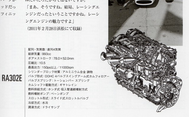
I used a generic description of the motor as its official title RE302E may be confused with the 1968 F1 car.
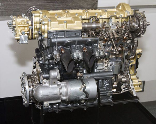
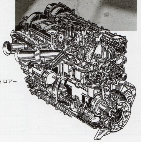
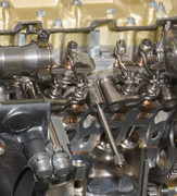
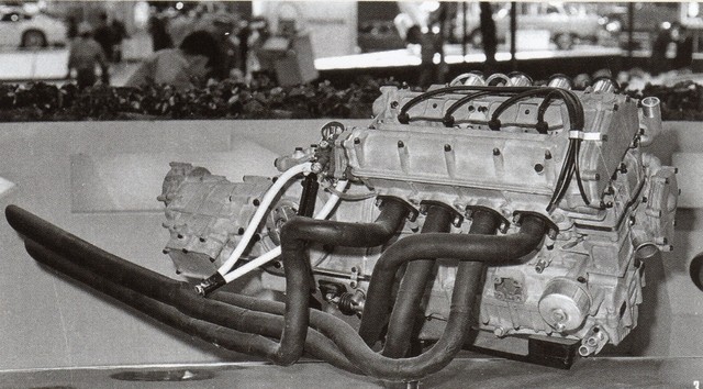
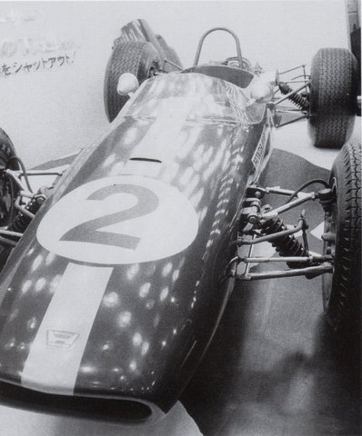
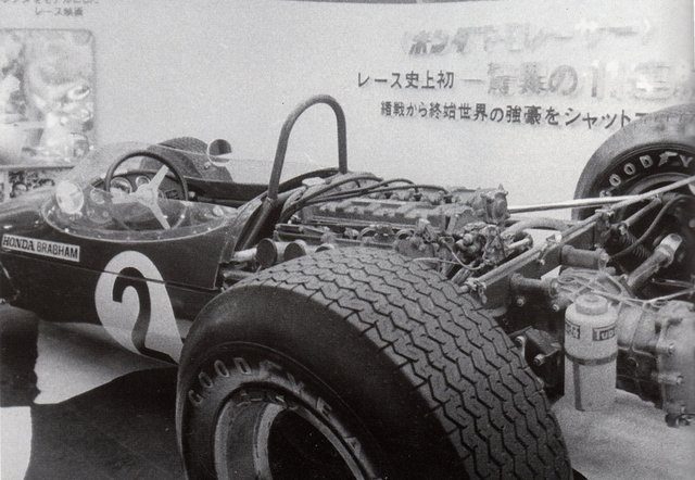
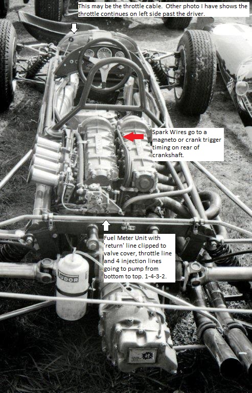
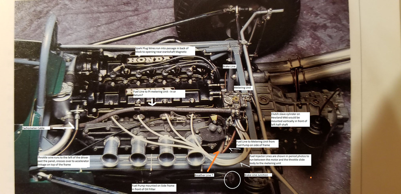
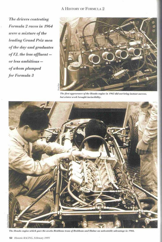
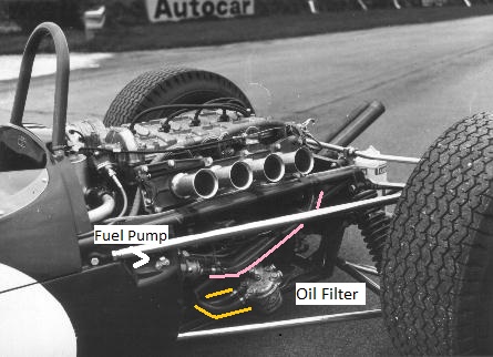
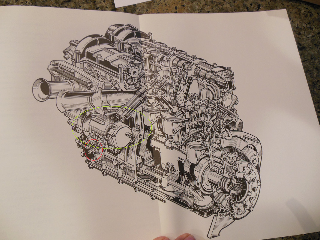
The Japanese model company Ebbro has recently released a very lovely 1/20 scale kit of the Brabham BT 18 Honda F2 from 1966. The kit does not include or show the ignition or the injection lines where they go into the metering unit for the injector or whatever Honda used in lieu of a rotating distributor. The engine, like the S800 motor, did not have a typical distributor. There are additional fuel pump lines I would like to trace as well. It appears that the coolant plumbing is included.
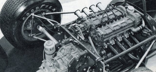
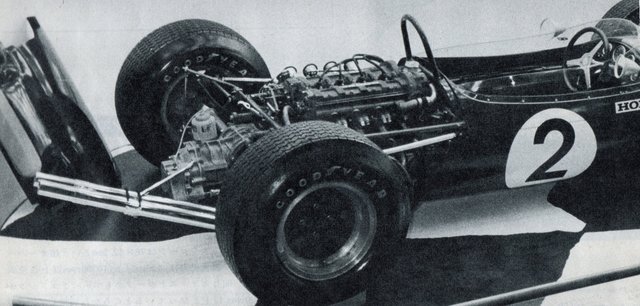
To my knowledge, there is the one complete Brabham Honda in the Honda collection.* This car was sent to Honda after the 1966 season. The on-line photos are either showing the car closed in the museum or the exhaust side which does not show the ignition/injection source points. There is a second motor, a cut-away motor in the collection but the on-line photos of it are of the right exhaust side with no lines or wires attached.
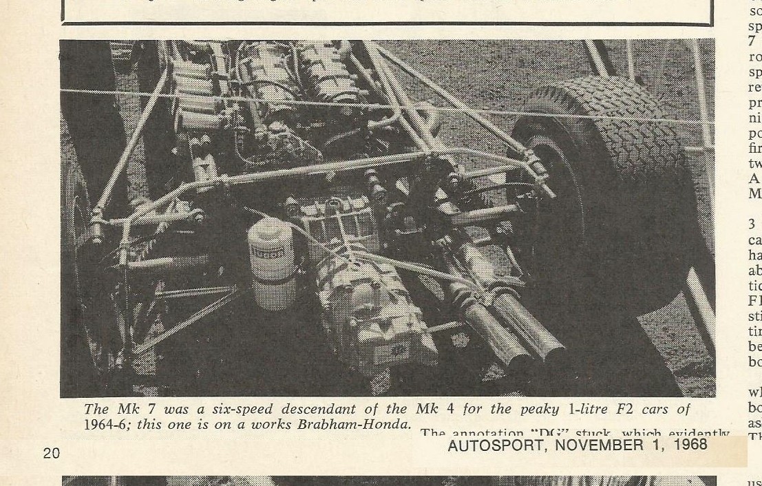
* Brabham ran two cars. After the 1966 season F2 went to the 1.6 liter formula and Honda left on a high note. (If you see a video of the car, it was a very high note) The second factory team car was recently for sale with a Lotus Twin Cam in. Other BT18's were sold to customers. I assume in 1966, these would have likely used Cosworth FCA or BRM P80's.
Considering Honda's overwhelming success in 1966 F2, I am surprised not much can be found on this motor. BTW, this motor is very different from that which was used in the BT16 in 1965.
Edited by DavidLayton, 06 December 2018 - 16:35.


