Jump to content


Photo
- - - - -

Strictly Technical: CVVD Continuously Variable Valve Duration


  • Please log in to reply
37 replies to this topic

#1 manolis

manolis
  • Member

  • 935 posts
  • Joined: May 03

Posted 29 April 2020 - 09:34

Hello all.


Quote from the official web-site of Hyundai: https://tech.hyundaimotorgroup.com/article/hyundai-announces-breakthrough-engine-that-answers-a-133-year-challenge/


Hyundai’s Breakthrough Engine that Answers a 133-year Challenge


01-776-x-515.png


Overcoming the performance-economy compromise

. . .


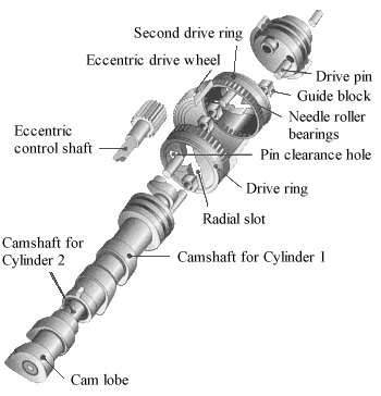
The world-first CVVD technology developed by the Hyundai Motor Group allows for control of infinitely variable valve durations. Furthermore, the technology achieved it with a relatively simple mechanical contraption to achieve reliability, while minimizing cost increase; truly an innovation.


06-776-x-440.png


The Hyundai Motor Group successfully created the most simply structured, mechanically-implemented CVVD mechanism, through countless iterations.


. . .


CVVD cams share similarities with existing engine cams, but the adjuster link shifts the axis and adjusts cam revolution speeds. Depending on how long the intake and exhaust valves stay open or closed, there are up to 1400 settings that the CVVD system can select from.


CVVLs also work with duration changes, but in terms of peer duration, the CVVL lift is less than half of CVVD. In the case of CVVL, changes in valve duration can hinder lift and result limit necessary air intake and exhaust. CVVD rectifies this limitation, allowing for valve lift with a much wider valve duration window.

The Hyundai Motor Group registered more than a hundred CVVD-related patents per regions around the world, including in Japan, China, and the European Union. More than 120 patents are registered in the U.S. alone.


CVVD is economic, fun to drive, and green


Existing variable valve technologies had to compromise between performance and economy. driving performance required a short valve overlap to maximize airflow, and fuel-economy required longer valve overlap to mitigate downstroke pump loss. Preexisting valve technologies could not achieve both and had to seek a middle-ground or compromise between the two.

CVVD is a breakthrough technology because it can optimize valve overlap duration for high-acceleration and high-economy driving needs, boosting performance and economy up to 4% and 5% respectively. The 5% boost in fuel economy based entirely on a valve system improvement is a giant breakthrough; 5% is the aggregate total of efficiency improvement achieved by all previous valve-timing control in the entirety of the combustion engine’s 133-year history.


End of Quote


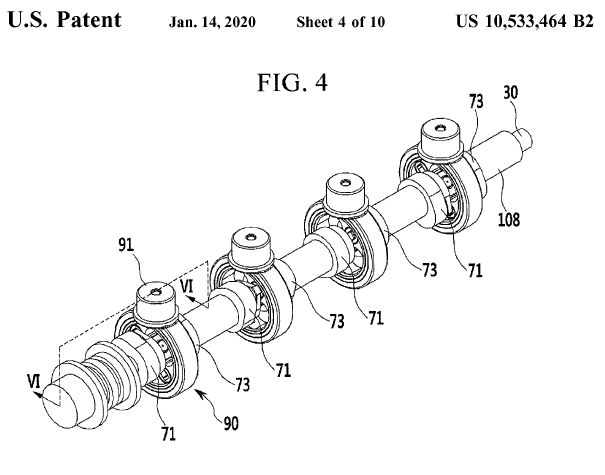
Here https://www.pattakon...i_US8813704.pdf  is the first US patent granted to Hyundai in 2011 for their CVVD, here https://www.pattakon..._US10533464.pdf is the latest US patent granted to Hyundai for their CVVD  


Quote from https://forums.autos...enigsegg/page-3


Desmo:

It feels like there will be an all-electric car fleet powered by fusion generators before any of these alternative valve systems are ever actually built and adopted at scale.  The Hyundai VVT system, however, is quite clever, gets most of the theoretically possible upsides, and it actually exists in numbers.


End of Quote


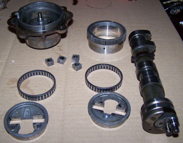
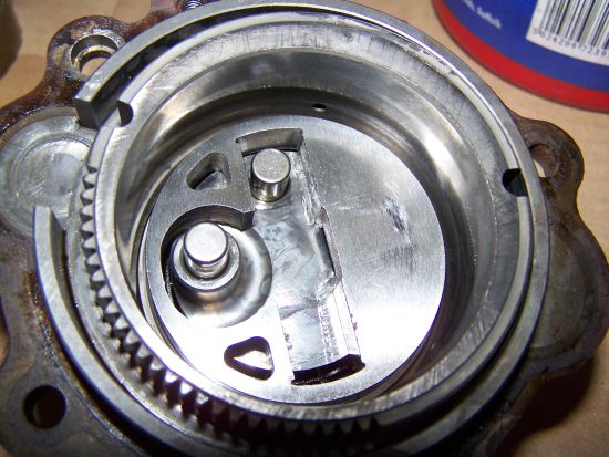
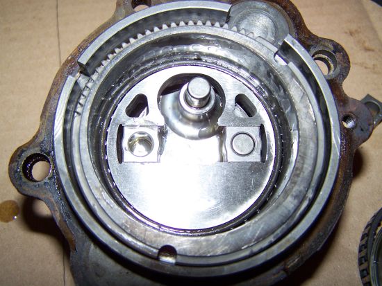
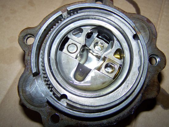
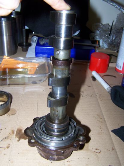
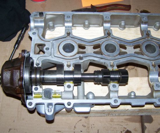
Here is the Rover VVC:
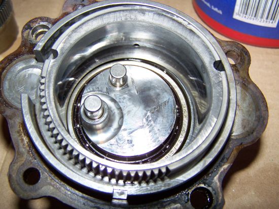
 

Rover_VVC_b.jpg


Rover_VVC.jpg


vvc1.jpg


vvc2.jpg


vvc3.jpg


vvc4.jpg


vvc5.jpg


vvc6.jpg


vvc8.jpg


vvc11.jpg


vvc31.jpg


The above photos are from http://forum.mg-rove...p?topic=41246.0


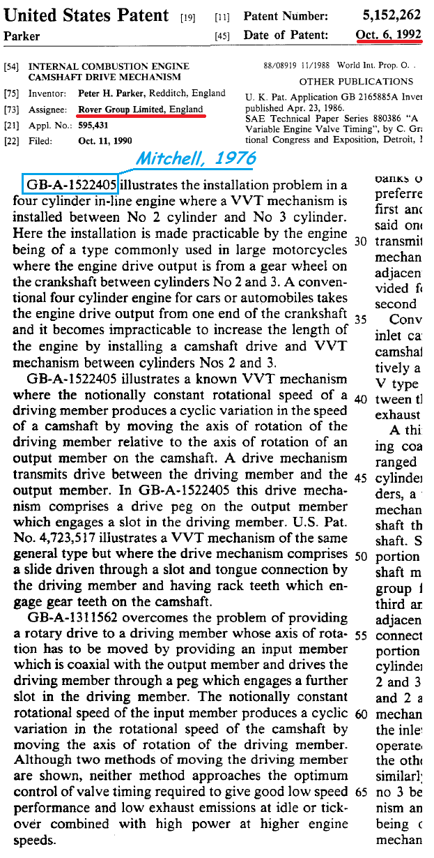
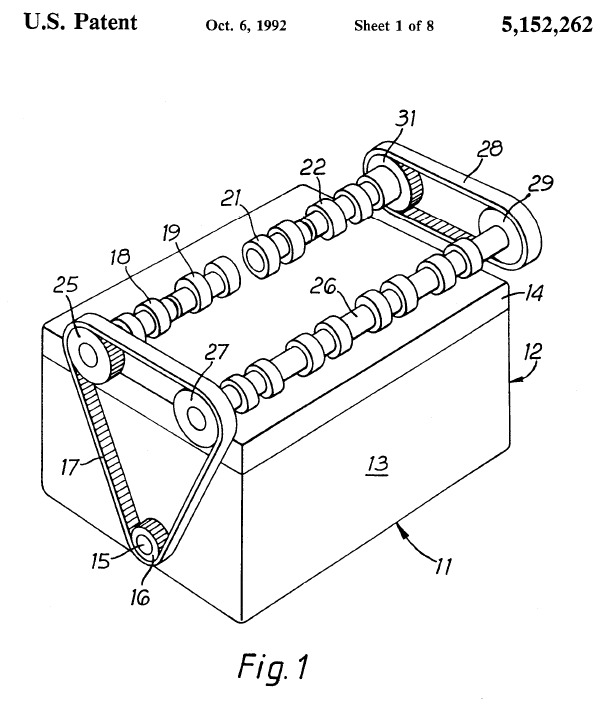
The US patent https://www.pattakon.../Rover_US_1.pdf  was granted in 1992 Peter Parker (Rover Group) for the above CVVD system (called VVC).


And here is the PatVVD (pattakon CVVD) presented at https://www.pattakon...pattakonVVD.htm :


PatVVD_fast.gif


The above animation shows the 24 "equivalent" camlobes when the "control" (explained in the following) makes a complete turn in steps of 15 degrees (15*24=360).

Here it is shown the working (the actual) cam lobe:


Working_Camlobe.png


wherefrom the "equivalent" cam lobes result. It is from an old (non CVVD) Hyundai engine and has roller cam follower.

Here it is shown the above working and two "equivalent" cam lobes:
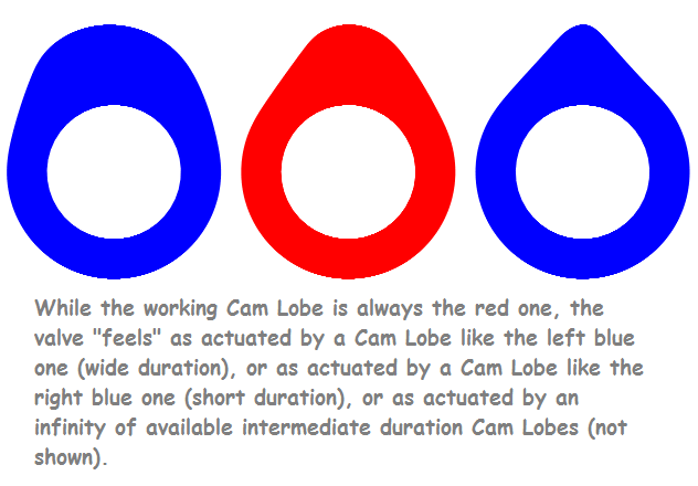
 

PatVVD_Working_and_Equivalent_Cam_Lobes.


Here the PatVVD on a four cylinder engine:
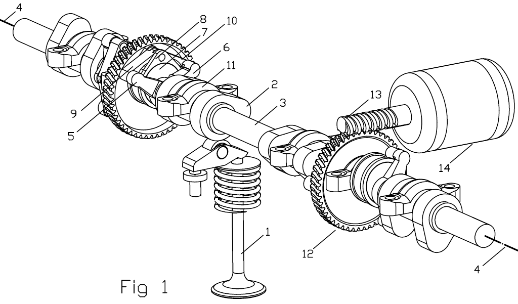
 

PatVVD_5.png


An interesting application of the PatVVD mechanism would be on a V-twin Desmo Ducati Panigale:
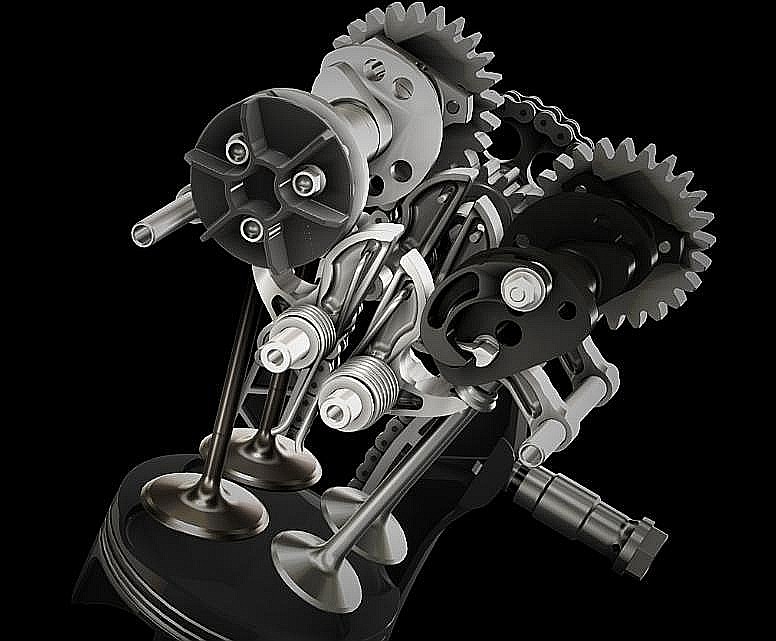


Ducati_Panigale_valve_train.jpg


the engine will remain as desmodromic as before, however its valve opening duration would widely increase (and decrease) on-the-fly.
As for the required "hardware" modification, it has to do only with the "connection" of the sprocket with the camshaf, say as shown below:
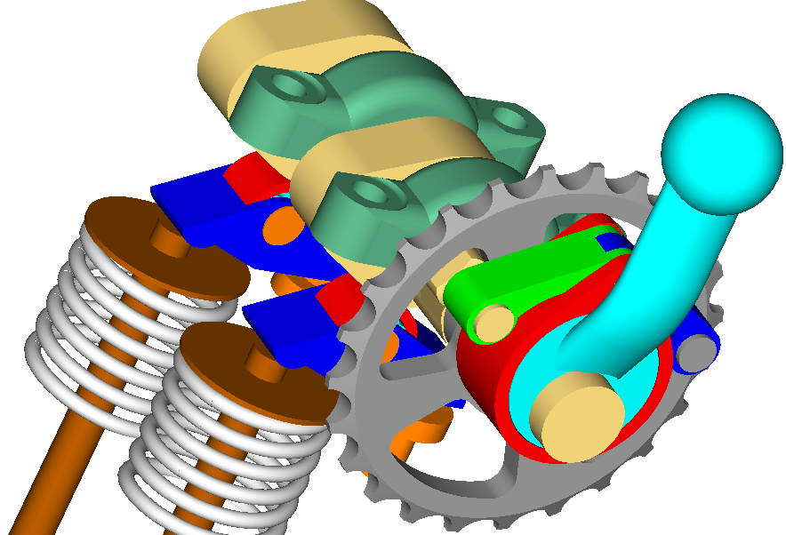
 

PatVVD_6.png


Thanks

Manolis Pattakos


Edited by manolis, 29 April 2020 - 10:05.


Advertisement

#2 gruntguru

gruntguru
  • Member

  • 7,683 posts
  • Joined: January 09

Posted 29 April 2020 - 22:06

Mr "Engineering Explained" makes the Hyundai system reasonably simple - as usual.
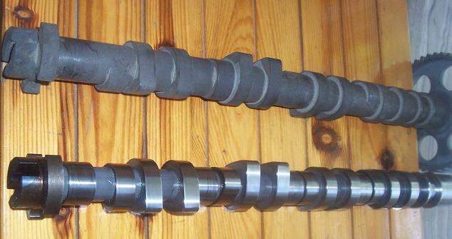
 

https://www.youtube....gdwUX1-w&t=500s


#3 Kelpiecross

Kelpiecross
  • Member

  • 1,730 posts
  • Joined: October 10

Posted 30 April 2020 - 03:50

Mr "Engineering Explained" makes the Hyundai system reasonably simple - as usual.


https://www.youtube....gdwUX1-w&t=500s


 I have already posted a link to this - the world would be a better place if they read my posts more carefully.  


#4 Kelpiecross

Kelpiecross
  • Member

  • 1,730 posts
  • Joined: October 10

Posted 30 April 2020 - 06:23

 The thing that surprises me most is that Hyundai makes no reference as "prior art"  to the Rover VVC  even though it appears to be almost a direct copy of it.    Sometimes I wonder just how the USPTO operates. 


 I presume your arrangement is a similar eccentric drive  system?  An animated drawing maybe? - I don't quite see how it works.  


 The Helical Cam does much the same - and is a thousand times simpler.  


#5 gruntguru

gruntguru
  • Member

  • 7,683 posts
  • Joined: January 09

Posted 01 May 2020 - 03:02


PatVVD_5.png


Does the mechanism require only two actuators for a four cylinder engine as suggested by this diagram?


#6 manolis

manolis
  • Member

  • 935 posts
  • Joined: May 03

Posted 01 May 2020 - 08:03

Hello Gruntguru.


Yes.


By the way:


In Fig. 1 the right pair of control pins is secured on a gearwheel 12 which is intermeshed with a worm gear 13, which is driven by a motor 14. 


The left pair of control pins are secured to another gearwheel (like 12) which can be driven by another worm gear (like 13), with the worm gear driven either by another motor (like 14) or by the same motor 14 through a pair of sprockets (one per worm gear) and a toothed belt engaging the sprockets.


The control pin remains at constant eccentricity from the rotation axis 4 of the cam and is displaced angularly (and not linearly) about the rotation axis 4.


Such an arrangement improves the compactness, the stiffness, the simplicity, the accuracy and the low cost of the mechanism: the bearings required to support / keep the mechanism are a series of coaxial bearings like those used for the mounting / support of a conventional camshaft; the holes in the cam and in the control pin are the bearings wherein the cam drive is supported, while the cam and the control pin are supported on the cylinder head by a series of coaxial bearings, like 11.


Thanks

Manolis Pattakos


Edited by manolis, 01 May 2020 - 08:58.


#7 manolis

manolis
  • Member

  • 935 posts
  • Joined: May 03

Posted 01 May 2020 - 08:47

Hello Kelpiecross


You write:

The thing that surprises me most is that Hyundai makes no reference as "prior art"  to the Rover VVC  even though it appears to be almost a direct copy of it.”   


They not only “forget” to mention Parker’s / Rover invention,

but Hyundai also claims they first put a CVVD in mass production.


Worse even, they talk for ”Hyundai’s Breakthrough Engine that Answers a 133-year Challenge”.


You also write:

“Sometimes I wonder just how the USPTO operates.”


USPTO is the best, by far, patent Office.


Having said that, the USPTO sucks.  


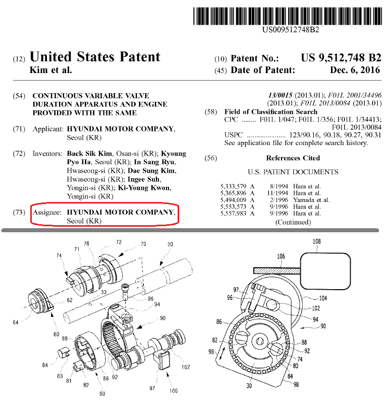
Hyundai Motor Company is the assignee of the following set of US-patents US8,813,704, US9,512,748, US9,822,674, US9,850,789, US9,856,758, US10,174,643, US10,533,464 that cover “their” CVVD.


Interestingly, all these patents (except the most recent one) have been examined / granted by the same USPTO Examiner.


We have bad experience with that guy. You can read our communication with him for the PatAIR US patent application.


While he grants generously patents to car companies, the same patents are refused to individuals.


You also write:

“I presume your arrangement is a similar eccentric drive  system?  An animated drawing maybe? - I don't quite see how it works.”


I presume your arrangement is a similar eccentric drive  system?  An animated drawing maybe? - I don't quite see how it works.  


 The Helical Cam does much the same - and is a thousand times simpler. “


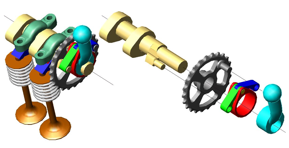
Explaining the patVVD:

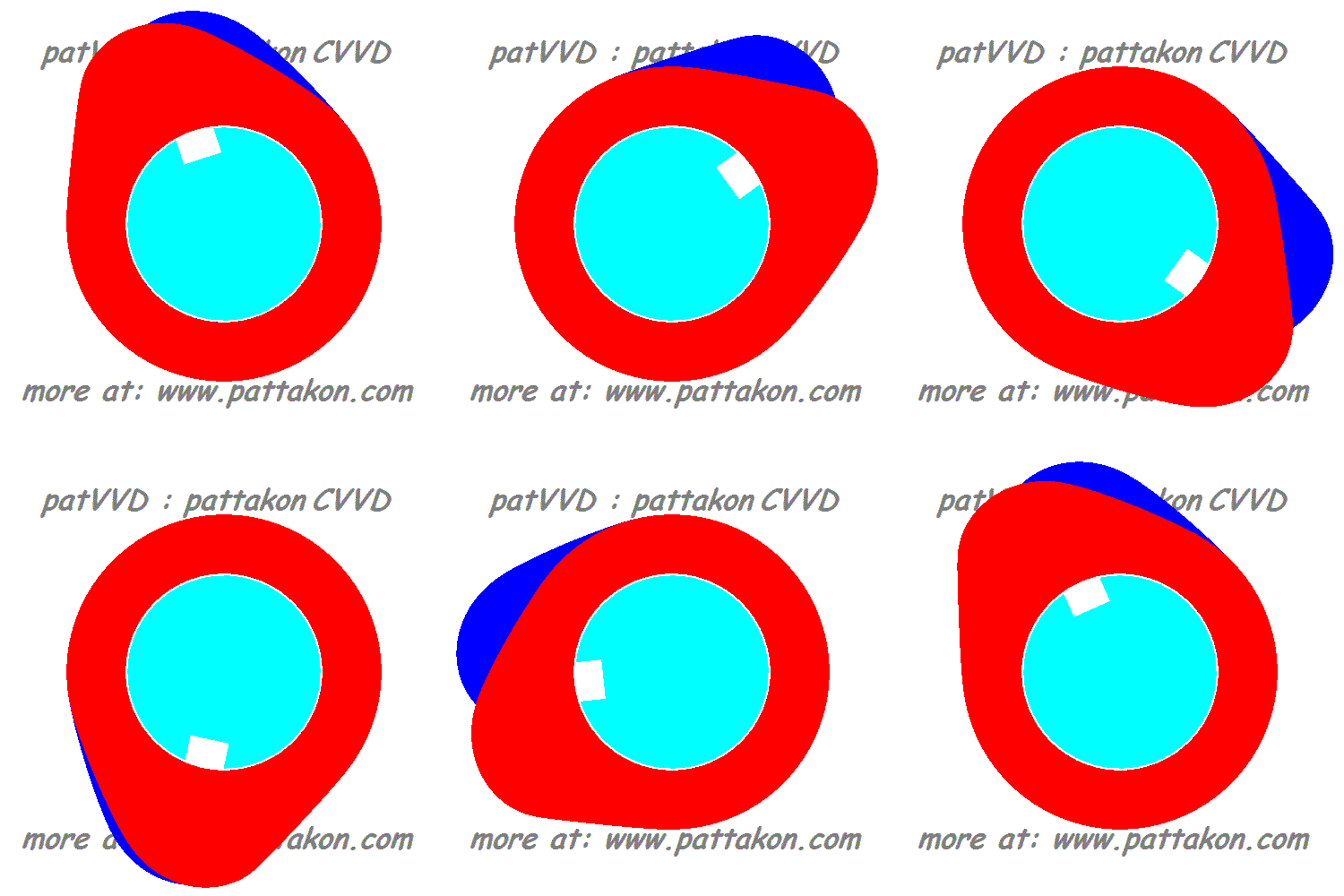
The cyan part is the cam shaft whereon a cam lobe is pivotally mounted; the cyam cam shaft rotates at constant angular velocity.

The patVVD mechanism (not shown here***) causes a fluctuation of the angular velocity of the cam lobe along a camshaft rotation.


PatVVD_explained.gif


(slow motion at https://www.pattakon...lained_slow.gif )


The animation has a slide per 6 degrees of camshaft rotation (or per 12 degrees of crankshaft rotation).

At a first position of the control pin (not shown) the camlobe (shown red in this case) rotates slowly when its nose passes over the "for more: www.pattakon.com" label (at bottom), and quickly when its nose passes over the "patVVD : pattakon CVVD" label (at top).

At a second position of the control pin, the camlobe (shown blue in this case) rotates quickly when its nose passes over the "for more: www.pattakon.com" label (at bottom), and slowly when its nose passes over the "patVVD : pattakon CVVD" label (at top).


If the valve actuator were where the bottom label is, the valve duration with the control pin at its first position (cam lobe red) would be more than 70 camshaft degrees longer than with the control pin at its second position (cam lobe blue).”


***the mechanism is explained by a windows “exe” animation at thebottompf the https://www.pattakon...pattakonVVD.htm web page.


Thanks

Manolis Pattakos


#8 gruntguru

gruntguru
  • Member

  • 7,683 posts
  • Joined: January 09

Posted 02 May 2020 - 03:32

Hello Kelpiecross


You write:

The thing that surprises me most is that Hyundai makes no reference as "prior art"  to the Rover VVC  even though it appears to be almost a direct copy of it.”   


They not only “forget” to mention Parker’s / Rover invention,

but Hyundai also claims they first put a CVVD in mass production.


Worse even, they talk for ”Hyundai’s Breakthrough Engine that Answers a 133-year Challenge”.


Apparently Hyundai's system is the first to combine CVVD and VVT. The Rover system did not have a "through shaft". It had a drive at each end and would have needed two cam phasers to achieve VVT. No doubt it could also have been designed with a "through shaft" like the Hyundai and the PatVVD.


#9 manolis

manolis
  • Member

  • 935 posts
  • Joined: May 03

Posted 03 May 2020 - 04:17

Hello Gruntguru.


You write:

“Apparently Hyundai's system is the first to combine CVVD and VVT. The Rover system did not have a "through shaft". It had a drive at each end and would have needed two cam phasers to achieve VVT. No doubt it could also have been designed with a "through shaft" like the Hyundai and the PatVVD.”


Even being the fist car maker to combine CVVD and VVT, does it justify claims like Hyundai’s Breakthrough Engine that Answers a 133-year Challenge”?


While 25 years ago the VVT’s were rare and expensive, now even small / cheap cars have a couple of VVT’s in the cylinder head.


Quote from http://www.sandsmuse...engine/vvc2.pdf


  • Rover VVC:
  •  
  • The basic concept was developed by a mr. Mitchell and it was published and patented back in 1973. However no one used it and it was forgotten until Rover re-discovered it. In 1989 Rover began experimenting with the system and in 1993 had developed a 1.4 litre version with VVC.
  • . . .
  • At this moment (Jan 2001) Rover is the only one who has a mass production engine with a variable duration of the camshaft. A bigger duration has more effect on power than opening and closing the valve later as with cam phasing systems. The Rover system is without a doubt far superior to all the cam phasing systems. It would be possible to incorporate a cam lobe switching mechanism to switch to a higher lift cam lobe as with Honda's VTEC. This would give the Rover engine the best of all worlds.


End of Quote                             


The last bold text is like pointing to the DVVA (desmodromicVVA):


DVVAphoto.jpg


with two differences:

  • the DVVA needs not valve springs (yet, if desirable, it can operate with valve springs, too),
  • it provides not only one more valve lift, but infinite (yet, if desirable, it can be limited to only two valve lifts, a normal and a higher ones) .


Here is the Rover VVC:


vvc5.jpg


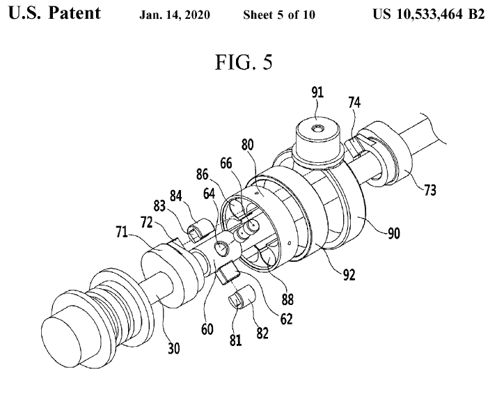
Here is a drawing from the last US patent granted to Hyundai (as the assignee) :


Hyundai_US10533464_Fig5.png


Spot on the 62 and 82 parts.


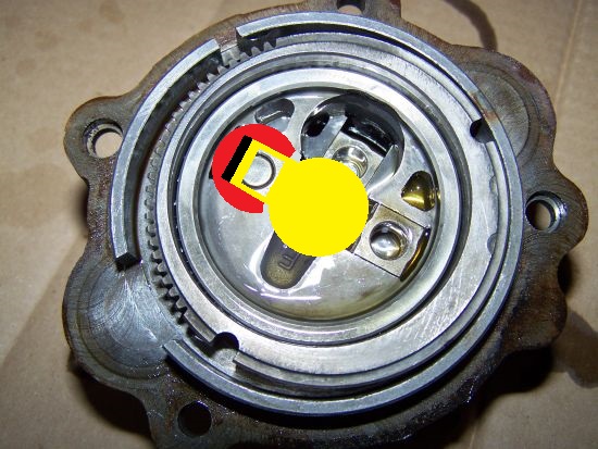
And here they are shown their difference:


vvc5mod.jpg


The red part is the 62, the yellow part is the 82.


The pin of Rover VVC has been moved outside, the slot of the Rover VVC has been moved inside.


Thanks

Manolis Pattakos


#10 gruntguru

gruntguru
  • Member

  • 7,683 posts
  • Joined: January 09

Posted 04 May 2020 - 02:24

No doubt the Rover patent has expired but it is still ridiculous that Hyundai can so blatantly copy it and stop others using the idea for some time. Does the Hyundai patent reference the prior art of Rover? I suppose you could copy the Rover system and claim that as your source in the face of any challenge from Hyundai.


Edited by gruntguru, 04 May 2020 - 02:26.


#11 manolis

manolis
  • Member

  • 935 posts
  • Joined: May 03

Posted 04 May 2020 - 06:10

Hello Gruntguru


You write:

"No doubt the Rover patent has expired but it is still ridiculous that Hyundai can so blatantly copy it and stop others using the idea for some time. Does the Hyundai patent reference the prior art of Rover? "


The following quote is from the USPTO (Unted States Patent and Trademark Office).


It is the "Background art / Related art / Prior art / State-of-the-art" section of each one of the seven US patents granted, so far, to Hyundai (as the assignee) for CVVD system. Compare them "line by line" / "word by word" 


Interestingly, there is no mention (at all) to Rover's VVC system and patent (US patent: US5,152,262), nor to other valve systems already providing variable duration without reducing the valve lift (say: Helical cam, DVVA etc).


These seven patents extend along a period of seven years.


It seems that during all these years neither Hyundai, nor the USPTO examiners (who's duty is exactly to know, or find out, the prior art, and judge based on the prior art), heard something about the existing prior art,even if it is in mass production for several decades (Rover VVC).


US 8,813,704


2. Description of Related Art

An internal combustion engine generates power by burning fuel in a combustion chamber in an air media drawn into the chamber. Intake valves are operated by a camshaft in order to intake the air, and the air is drawn into the combustion chamber while the intake valves are open. In addition, exhaust valves are operated by the camshaft, and a combustion gas is exhausted from the combustion chamber while the exhaust valves are open.

Optimal operation of the intake valves and the exhaust valves depends on a rotation speed of the engine. That is, an optimal lift or optimal opening/closing timing of the valves depends on the rotation speed of the engine. In order to achieve such optimal valve operation depending on the rotation speed of the engine, various researches, such as designing of a plurality of cams and a continuous variable valve lift (CVVL) that can change valve lift according to engine speed, have been undertaken.

Also, in order to achieve such an optimal valve operation depending on the rotation speed of the engine, research has been undertaken on a continuously variable valve timing (CVVT) apparatus that enables different valve timing operations depending on the engine speed. The general CVVT may change valve timing with a fixed valve opening duration.

However, the general CVVL and CVVT are complicated in construction and are expensive in manufacturing cost.

The information disclosed in this Background section is only for enhancement of understanding of the general background of the invention and should not be taken as an acknowledgement or any form of suggestion that this information forms the prior art already known to a person skilled in the art.”


US 9,512,748


BACKGROUND

An internal combustion engine generates power by burning a fuel in a combustion chamber by drawing air into the chamber. Intake valves intake the air by rotation of a camshaft, and the air is drawn into the combustion chamber while the intake valves are opened. In addition, exhaust valves allows combustion gas out by the rotation of the camshaft, and the gas is exhausted from the combustion chamber while the exhaust valves are opened.

The optimal operation of the intake valves and the exhaust valves depends on a rotation speed of the engine. In order to achieve such an optimal valve operation depending on the rotation speed of the engine, various researches, such as designing of a plurality of cams and a continuous variable valve lift (CVVL) that can change valve lift according to engine speed, have been undertaken.

Further, in order to achieve such an optimal valve operation depending on the rotation speed of the engine, a continuously variable valve timing (CVVT) apparatus that enables different valve timing operations depending on the engine speed has been developed. The general CVVT may change valve timing with a fixed valve opening duration.

However, the general CVVL and CVVT have a complicated structure and manufacturing cost is high.

The above information disclosed in this Background section is only for enhancement of understanding of the background of the disclosure, and therefore, it may contain information that does not form the prior art that is already known in this country to a person of ordinary skill in the art.”


US 9,822,674


Description of Related Art

An internal combustion engine generates power by burning fuel in a combustion chamber in an air media drawn into the chamber. Intake valves are operated by a camshaft in order to intake the air, and the air is drawn into the combustion chamber while the intake valves are open. In addition, exhaust valves are operated by the camshaft, and a combustion gas is exhausted from the combustion chamber while the exhaust valves are open.

Optimal operation of the intake valves and the exhaust valves depends on a rotation speed of the engine. That is, an optimal lift or optimal opening/closing timing of the valves depends on the rotation speed of the engine. In order to achieve such optimal valve operation depending on the rotation speed of the engine, various researches, such as designing of a plurality of cams and a continuous variable valve lift (CVVL) that can change valve lift according to engine speed, have been undertaken.

Also, in order to achieve such an optimal valve operation depending on the rotation speed of the engine, research has been undertaken on a continuously variable valve timing (CVVT) apparatus that enables different valve timing operations depending on the engine speed. The general CVVT may change valve timing with a fixed valve opening duration.

However, the general CVVL and CVVT are complicated in construction and are expensive in manufacturing cost.

The information disclosed in this Background of the Invention section is only for enhancement of understanding of the general background of the invention and should not be taken as an acknowledgement or any form of suggestion that this information forms the prior art already known to a person skilled in the art.”


US 9,850,789


Description of Related Art

An internal combustion engine generates power by burning fuel in a combustion chamber in an air media drawn into the chamber. Intake valves are operated by a camshaft in order to intake the air, and the air is drawn into the combustion chamber while the intake valves are open. In addition, exhaust valves are operated by the camshaft, and a combustion gas is exhausted from the combustion chamber while the exhaust valves are open.

Optimal operation of the intake valves and the exhaust valves depends on a rotation speed of the engine. That is, an optimal lift or optimal opening/closing timing of the valves depends on the rotation speed of the engine. In order to achieve such optimal valve operation depending on the rotation speed of the engine, various researches, such as designing of a plurality of cams and a continuous variable valve lift (CVVL) that can change valve lift according to engine speed, have been undertaken.

Also, in order to achieve such an optimal valve operation depending on the rotation speed of the engine, research has been undertaken on a continuously variable valve timing (CVVT) apparatus that enables different valve timing operations depending on the engine speed. The general CVVT may change valve timing with a fixed valve opening duration.

However, the general CVVL and CVVT are complicated in construction and are expensive in manufacturing cost.

The information disclosed in this Background of the Invention section is only for enhancement of understanding of the general background of the invention and should not be taken as an acknowledgement or any form of suggestion that this information forms the prior art already known to a person skilled in the art.”


US 9,856,758


Description of Related Art

An internal combustion engine generates power by burning fuel in a combustion chamber in an air media drawn into the chamber. Intake valves are operated by a camshaft in order to intake the air, and the air is drawn into the combustion chamber while the intake valves are open. In addition, exhaust valves are operated by the camshaft, and a combustion gas is exhausted from the combustion chamber while the exhaust valves are open.

Optimal operation of the intake valves and the exhaust valves depends on a rotation speed of the engine. That is, an optimal lift or optimal opening/closing timing of the valves depends on the rotation speed of the engine. In order to achieve such optimal valve operation depending on the rotation speed of the engine, various researches, such as designing of a plurality of cams and a continuous variable valve lift (CVVL) that can change valve lift according to engine speed, have been undertaken.

Also, in order to achieve such an optimal valve operation depending on the rotation speed of the engine, research has been undertaken on a continuously variable valve timing (CVVT) apparatus that enables different valve timing operations depending on the engine speed. The general CVVT may change valve timing with a fixed valve opening duration.

However, the general CVVL and CVVT are complicated in construction and are expensive in manufacturing cost.

The information disclosed in this Background of the Invention section is only for enhancement of understanding of the general background of the invention and should not be taken as an acknowledgement or any form of suggestion that this information forms the prior art already known to a person skilled in the art.”


US 10,174,643


Description of Related Art

An internal combustion engine generates power by burning fuel in a combustion chamber in an air media drawn into the chamber. Intake valves are operated by a camshaft in order to intake the air, and the air is drawn into the combustion chamber while the intake valves are open. In addition, exhaust valves are operated by the camshaft, and a combustion gas is exhausted from the combustion chamber while the exhaust valves are open.

Optimal operation of the intake valves and the exhaust valves depends on a rotation speed of the engine. That is, an optimal lift or optimal opening/closing timing of the valves depends on the rotation speed of the engine. In order to achieve such optimal valve operation depending on the rotation speed of the engine, various researches, such as designing of a plurality of cams and a continuous variable valve lift (CVVL) that can change valve lift according to engine speed, have been undertaken.

Also, in order to achieve such an optimal valve operation depending on the rotation speed of the engine, research has been undertaken on a continuously variable valve timing (CVVT) apparatus that enables different valve timing operations depending on the engine speed. The general CVVT may change valve timing with a fixed valve opening duration.

However, the general CVVL and CVVT are complicated in construction and are expensive in manufacturing cost.

The information disclosed in this Background of the Invention section is only for enhancement of understanding of the general background of the invention and may not be taken as an acknowledgement or any form of suggestion that this information forms the prior art already known to a person skilled in the art.”


US 10,533,464


Description of Related Art

An internal combustion engine generates power by burning fuel in a combustion chamber in an air media drawn into the chamber. Intake valves are operated by a camshaft in order to intake the air, and the air is drawn into the combustion chamber while the intake valves are open. In addition, exhaust valves are operated by the camshaft, and a combustion gas is exhausted from the combustion chamber while the exhaust valves are open.

Optimal operation of the intake valves and the exhaust valves depends on a rotation speed of the engine. That is, an optimal lift or optimal opening/closing timing of the valves depends on the rotation speed of the engine. In order to achieve such optimal valve operation depending on the rotation speed of the engine, various researches, such as designing of a plurality of cams and a continuous variable valve lift (CVVL) that can change valve lift according to engine speed, have been undertaken.

Also, in order to achieve such an optimal valve operation depending on the rotation speed of the engine, research has been undertaken on a continuously variable valve timing (CVVT) apparatus that enables different valve timing operations depending on the engine speed. The general CVVT may change valve timing with a fixed valve opening duration.

However, the general CVVL and CVVT are complicated in construction and are expensive in manufacturing cost.

The information disclosed in this Background of the Invention section is only for enhancement of understanding of the general background of the invention and should not be taken as an acknowledgement or any form of suggestion that this information forms the prior art already known to a person skilled in the art.”


Thanks

Manolis Pattakos


#12 manolis

manolis
  • Member

  • 935 posts
  • Joined: May 03

Posted 05 May 2020 - 04:52


Quote from http://www.sandsmuse...engine/vvc2.pdf

  • Rover VVC
  •  
  • The basic concept was developed by a mr. Mitchell and it was published and patented back in 1973. However no one used it and it was forgotten until Rover re-discovered it. In 1989 Rover began experimenting with the system and in 1993 had developed a 1.4 litre version with VVC.
  •  
  • At this moment (Jan 2001) Rover is the only one who has a mass production engine with a variable duration of the camshaft. A bigger duration has more effect on power than opening and closing the valve later as with cam phasing systems. The Rover system is without a doubt far superior to all the cam phasing systems. It would be possible to incorporate a cam lobe switching mechanism to switch to a higher lift cam lobe as with Honda's VTEC. This would give the Rover engine the best of all world.


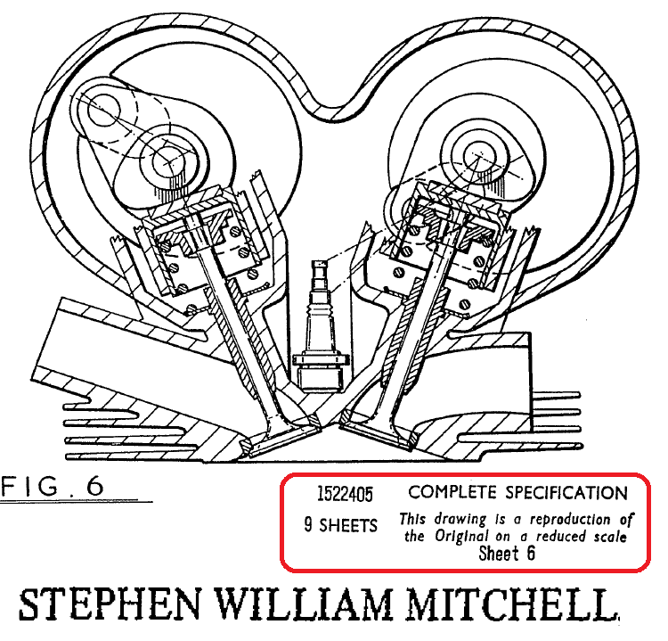
Here is a drawing from the patent of Mitchell, where the patent of Rover / Parket was based on:


Mitchell.png.


The complete document of Mitchell's patent is at https://www.pattakon...l_GB1522405.pdf


Thanks

Manolis Pattakos


Edited by manolis, 05 May 2020 - 04:54.


#13 manolis

manolis
  • Member

  • 935 posts
  • Joined: May 03

Posted 06 May 2020 - 11:03

Hello all.


The following animation, added to the patVVD web page at https://www.pattakon...pattakonVVD.htm , may be useful in understanding the patVVD mechanism


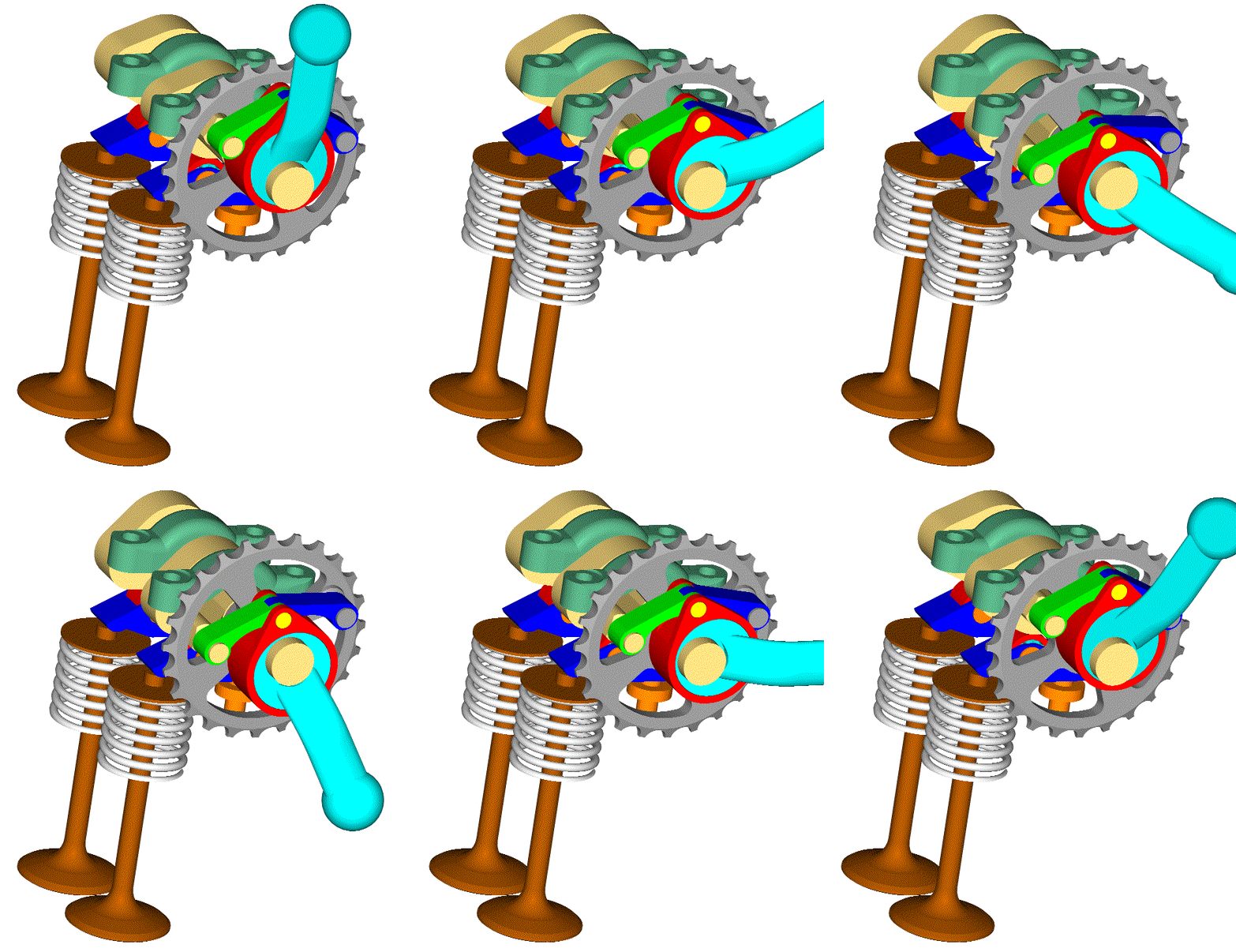
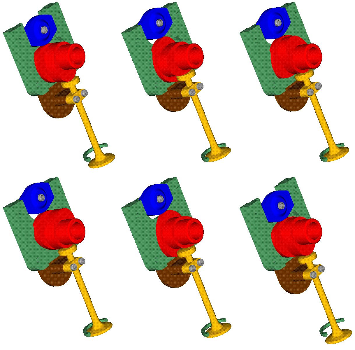
PatVVD_Control_Lever.gif


The control lever (cyan) is displaced at six different angles about the camshaft rotation axis.

Each angle of the control lever defines a different "valve lift profile" the valves have to follow during the rotation of the sprocket:


At https://www.pattakon..._Lever_slow.gif is the above animation at slow motion.


Here the sprocket rotates with the control lever (cyan) immovable:


PatVVD_Run.gif


At https://www.pattakon...VD_Run_slow.gif is the above animation at slow motion.


Thanks

Manolis Pattakos


Edited by manolis, 06 May 2020 - 15:04.


#14 manolis

manolis
  • Member

  • 935 posts
  • Joined: May 03

Posted 09 May 2020 - 05:01

Hello all.


Quote from the same discussion in another forum:


PlatinumZealot:


This article explains how Hyundai has gotten away with their claim to be the first...Sly marketing by use of word tricks is how.

https://www.autoweek...valve-duration/


End of Quote


Quote from Autoweek / Robin Warner:


It was Rover, not Hyundai that did it first, and this video explains it.


Earlier this year, I wrote about the very first Continuously Variable Valve Duration, or CVVD, system from Hyundai. I claimed it to be the first production engine with the technology. As did Jason Fenske of Engineering Explained in his recent video about the technology. And, turns out, we were both wrong.


End of Quote


In the above video, at 4:16, Peter O’Tool says for the VVC system: “looks extremely promising, so much that the design was patented to ensure it couldn’t be stolen”


In their patent, Rover does mention Mitchell’s patent as the closest prior art:


Rover_Mitchell.png


The conclusions are yours.


*******************


For the patVVD the following drawing:


PatVVD_6_explode.png


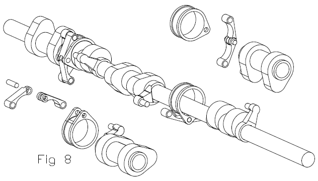
shows the simplicity and compactness of the system as applied to the cylinder head(s) of a single cylinder, or a boxer or Vee twin (like, say, the BMW GSR, or like the Ducati Panigale V-2).


The eccentric control pin (which is integral with the control lever, both cyan) is directly supported on the camshaft (beige), with the three links (or connecting rods; red, green and blue) of the mechanism being directly supported on the camshaft (beige), sprocket (gray) and control pin (cyan).


Count how many more parts (and “accurate” support points) are required for replacing the above patVVD by Hyundai’s CVVD:


Hyundai_US9512748.png


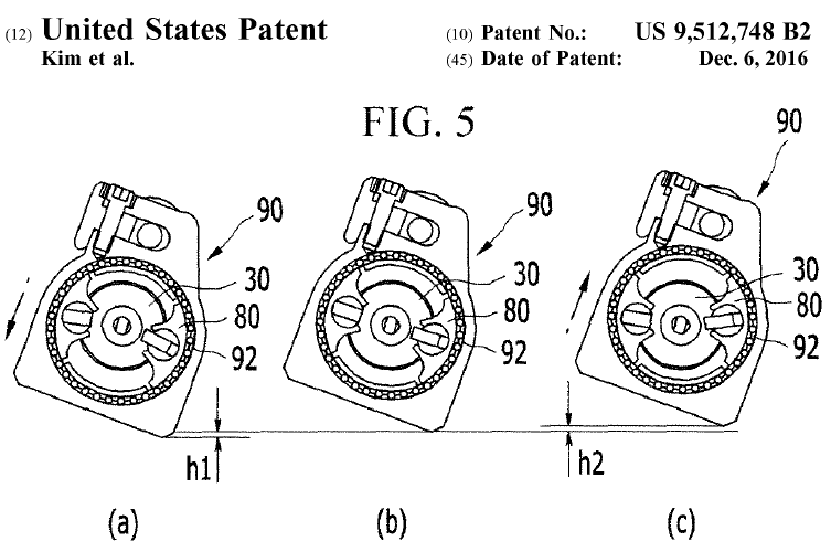
Hyundai_US9512748_Fig5.png


The part 102 is a “crankshaft” (a shaft having eccentric pins) rotatably mounted on its “own” series of bearings on the cylinder head. Each eccentric pin of this “crankshaft” forms a “scotch yoke” with its respective “frame” 90.

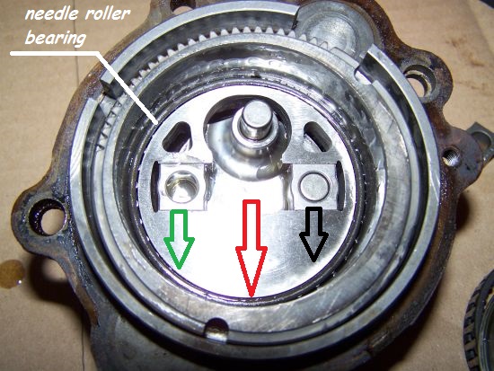
Inside the frame 90 it is a needle roller bearing of big diameter (some 3.5 times larger than the diameter of the shaft whereon the cams are pivotally mounted).


Why Hyundai (and Rover) need the big diameter needle roller bearing?


Here are two photos of the Rover VVC mechanism (spot on the two big needle roller bearings):


vvc1.jpg


vvc4mod.jpg


The black arrow at right is the force applied by the right pin/rectangle (i.e. the drive shaft) to the intermediate “disk”.
The green arrow at left is the reaction force from the respective cam (i.e. the driven shaft) to the intermediate “disk”.
The red arrow is the total force loading the bearing through which the intermediate “disk” is rotatably mounted on the eccentric control ring (that with the teeths at a portion of its periphery).
The total force (red) is about twice as strong as the driving force (black) and acts on a big diameter bearing; these make a “needle roller bearing” obligatory.


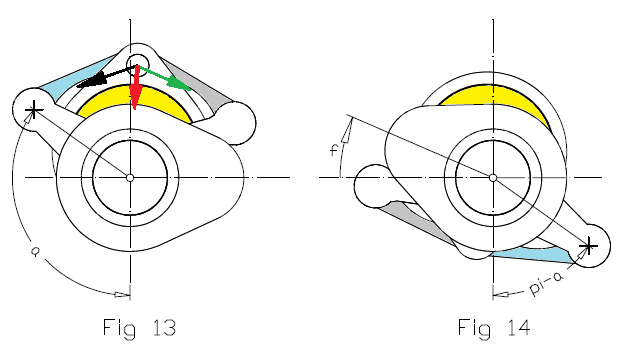
Here is a drawing of the PatVVD:


PatVVD_7_mod.png
 

The red arrow represents the total force; the total force is substantially smaller than each of the “driving” / ”driven” forces.

The diameter of the bearing (external diameter of the yellow “control” pin) whereon the total force acts is substantially smaller (say, two times the cam shaft diameter).

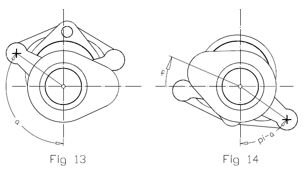
After 180 degrees of rotation (Fig 14), the wider angle between the cyan and the gray links / rods reduces substantially the total force on the bearing.

According the previous the use of a needle roller bearing is not necessary / mandatory / useful.

The mechanism of the PatVVD is more compact, more robust, more efficient (reduced friction loss and wear) and simpler / cheaper than Hyundai’s CVVD and Rover’s VVC .


One more thing: the “eccentricity” of the control pin of the PatVVD can be substantially larger than the “eccentricity” in the Rover VVC and in the Hyundai CVVD (the h1 and h2 in the Fig. 5 ofHyundai).

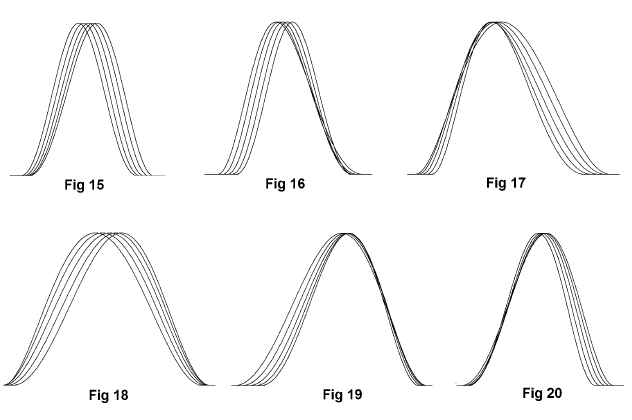
This allows a smaller rotation of the control pin (or control lever).

For instance, each of the following sets of valve lift profiles corresponds to 60 degrees of control lever rotation:


PatVVD_Valve_Lifts_60_deg.png


For applications without a VVT (like, say, high revving motorcycle engines, like cheap engines etc), the right choice of the region of the rotation angle of the control pin (or control lever) compensates the lack of a VVT (variableValve Timing).


Hello Kelpiecross.


You write:

“I presume your arrangement is a similar eccentric drive  system?  An animated drawing maybe? - I don't quite see how it works.  

 The Helical Cam does much the same - and is a thousand times simpler.


Were the animated drawings explanatory?


I hope you now understand how the patVVD works.


As compared to the Helical Cam (or William Camshaft), the patVVD uses only one cam lobe, the maximum acceleration and jerk are substantially lower at high revs (wherein large durations are required), the design is way simpler (and so cheaper), and the control is by far easier /accurate.


"A thousand times simpler" ? The Helical Cam from the patVVA?


Do I miss something?


By the way, Is it obvious how easily the patVVD can add variable duration to a Desmodromic Ducati Panigele V-twin? 

Think if this is possible with a Helical Cam.

Thanks
Manolis Pattakos


#15 desmo

desmo
  • Tech Forum Host

  • 31,288 posts
  • Joined: January 00

Posted 09 May 2020 - 15:11

Did Rover actually produce their VVT or just take steps to make it illegal for others to? If the latter, not terribly impressive.


#16 manolis

manolis
  • Member

  • 935 posts
  • Joined: May 03

Posted 09 May 2020 - 16:49

Hello Desmo.


You write:

“Did Rover actually produce their VVT or just take steps to make it illegal for others to? If the latter, not terribly impressive.”


Rover’s VVC system was in production for several years.


You can still buy used MG having the VVC system.


***********


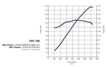
EDIT


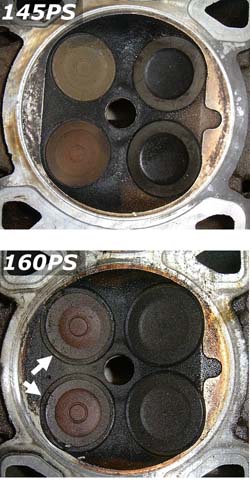
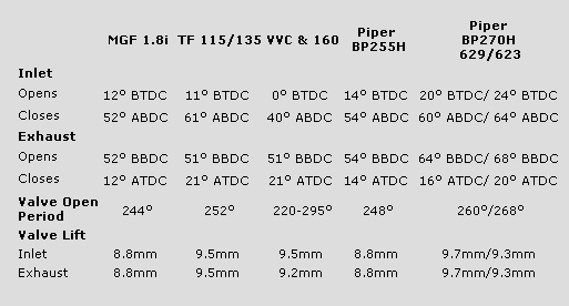
Quote from http://mgf.ultimatem...ine_options.htm


VVC_ultimatemg160ps_powercurve.jpg


VVC_ultimatemg_cylinderhead_145v160_w250


VVC_ultimatemgcam_timing_comparison.jpg


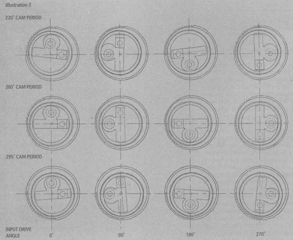
Spot on the "220-295 degrees "Valve Open Period" of the "VVC"


EDIT END


***********


A characteristic of the Rover VVC is the continuous variation of the valve opening duration.


The contemporary V-TEC of Honda was not better.

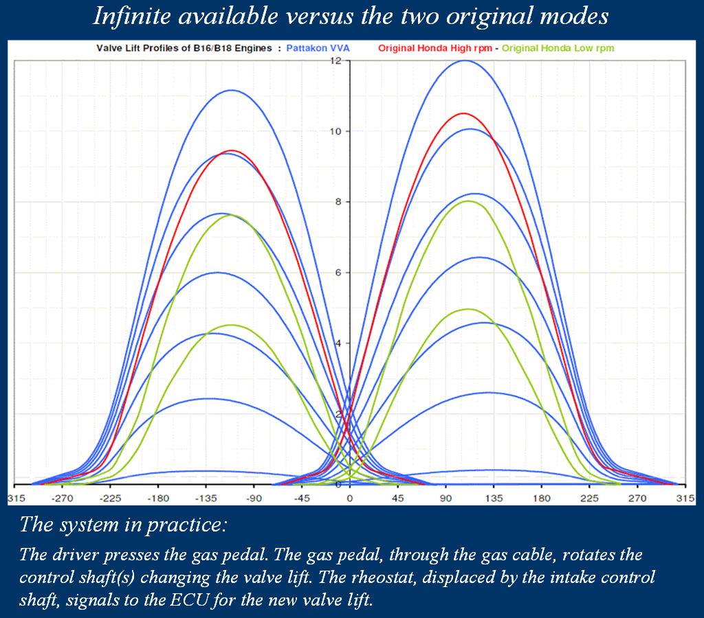
It provides more power but it has only two (instead of infinite) modes of operation:


**********


EDIT


Valve_Lift_Profiles_VVA_roller_vs_Origin


the red curves are the high-rpm valve lift profiles of the Honda V-TEC (B16A2 engine), the green curves are the low-rpm valve lift profiles (different for each valve) of the HondaV-TEC)


EDIT END


*************


with a deep, and dangerous for the average driver, torque hole at the transition point (a little after 5,000rpm).


Hyundai’s CVVD uses –more or less – the same mechanism.


But Rover’s VVC design had a “flaw”: it divides the camshaft into two separate (independent) parts, making the transmission from the crankshaft to the camshaft an “adventure”:


Rover_VVC_Divided_Camshaft.png


The drawing is from Rover’s patent; the 26 is the exhaust camshaft.


The Rover VVC controls the duration of the intake valve opening (i.e. for how many crankshaft degrees the intake valve will stay open).


If you want to control the timing, too (i.e. to advance or delay, for a few crankshaft degrees, all the intake valve events), you need a pair of VVT’s (Variable Valve Timing or Phaser), one inside the sprocket 25 and another inside the sprocket 31.


The design of Hyundai’s CVVD needs only one phaser and avoids the additional sprockets (29 and 31) and the additional tooth belt (28) of the Rover VVC.

This is so because on the same single-piece shaft(the 108 in the following drawing from a US patent of Hyundai) they are mounted all the intake cam lobes of the engine:


Hyundai_Shaft.png

.

This is the only “breakthrough” Hyundai can claim; not the single-piece shaft (it was already known) but the use of a single VVT instead of the two required by the Rover VVC system…


As the Hyundai CVVD,

similarly the pattakon patVVD needs only one phaser and avoids the additional sprockets (29 and 31) and the additional tooth belt (28) of the Rover VVC.


PatVVD_8.png


Thanks

Manolis Pattakos

http://mgf.ultimatem...ine_options.htm


Edited by manolis, 10 May 2020 - 06:14.


#17 manolis

manolis
  • Member

  • 935 posts
  • Joined: May 03

Posted 10 October 2020 - 03:31


 The Helical Cam does much the same - and is a thousand times simpler.  


Manny  - my comment on your latest engine idea - Eh? 


Thanks Kelpiecross.


The second quote is from the "GoFly / BOEING . . ." thread and is for the PatVRA mechanism:


PatVRA_6C.png


which is, more or less, the same with the mechanism used in the PatVVD:


PatVVD_7.png


(with the latter working under loads belonging in another class of magnitude: many many times lower).


The Williams Cam "does less" because it puts a "constant lift" (variable duration) portion at the top of the "valve lift vs crank angle" curve (profile) increasing the loads and the wear.


Besides, the Williams Cam system is not "a thousand times simpler", not even simpler. Actually it is more complicated if you think of the control mechanism it requires.


Thanks

Manolis Pattakos


Edited by manolis, 10 October 2020 - 03:34.


#18 Kelpiecross

Kelpiecross
  • Member

  • 1,730 posts
  • Joined: October 10

Posted 11 October 2020 - 05:07

Manny it is certainly a clever and interesting idea - but (a big "but") I think it solves a problem that really isn't a problem.  Unless I have totally missed the point  - what advantages do you claim it has over a typical crankshaft/engine?


 As for the Helical Cam (- who mentioned the HC?)   You have made much of the acceleration rate over the  shoulder of the lobe onto the constant radius area -   this was only for the prototype - cam grinders really only  work with profiles they have "masters" for - anything unusual is  very difficult for them - the HC has the best profile that was possible at the time.  Clearly the profile can be made without  these points of sudden acceleration/deceleration - and you know cam theory - you know this is possible.   Overall the profile can be juggled so that the excess acceleration is shared around.  The acceleration would  would maybe a bit higher than normal/or the lift a bit lower - but still within normal limits. 

 As for the "complicated" control system - an hydraulic cylinder moves back and forth by less than an inch to adjust the duration - not exactly "complicated". 

 The HC has recently been getting a bit of interest from academic sources - it is starting to become known as as one of the acceptable/realistic/possible methods of achieving variable duration.


  The MG system of VVT basically failed because the continual reversals of load on the lobes caused the sliding components to wear rapidly - and I think Hyundai will have the same problem ultimately.  Your system is probably much better with its swivelling/rotating  joints but still I think will finally have wear problems.  And it looks like a mad dog's breakfast - very complex.          


Edited by Kelpiecross, 11 October 2020 - 05:10.


#19 manolis

manolis
  • Member

  • 935 posts
  • Joined: May 03

Posted 11 October 2020 - 08:16

Hello Kelpiecross.


You write:

“Overall the profile can be juggled so that the excess acceleration is shared around.  The acceleration would  would maybe a bit higher than normal/or the lift a bit lower - but still within normal limits.”


If the Helical Cam (HC) is to operate at short valve durations (say, 200 crank degrees), the above cannot be done.

For short valve durations and reasonable lift, you need abrupt opening and closing ramps and “sharp nose” of the cam. These come with high acceleration and jerk.


In comparison, the Rover’s VVC (now Hyundai CVVD) and the PatVVD extend smoothly the valve lift profile reducing substantially the maximum acceleration and jerk at the long valve durations (where the engine is to run at high revs).


You also write:

“As for the "complicated" control system - an hydraulic cylinder moves back and forth by less than an inch to adjust the duration - not exactly "complicated". 

 The HC has recently been getting a bit of interest from academic sources - it is starting to become known as as one of the acceptable/realistic/possible methods of achieving variable duration.”


The only successful hydraulic system, so far, is the MultiAir / UniAir / TwinAir of FIAT / Alfa Romeo / Chrysler.

It is successful because it is an “on / off” hydraulic system.

The electronic controller triggers an electromagnetic valve to open a hole to discharge the hydraulic liquid.

If you delay the trigger pulse, the opening of the hole delays, if you advance the electronic trigger pulse the opening of the hole happens earlier.

The high accuracy of the MultiAir / UniAir / TwinAir comes from the electronic system, from the on / off operation of the hydraulic system and from the feedback to the ECU.


In the HC system you need a continuous and accurate control over the movable “semi-cams”, without lash at both directions. This is neither simple, nor easy, nor cheap.


This is why I asked if there are some drawings of the full HC system (the hydraulics included) of a straight four HC car engine.

Only having the complete system design you can say it is simple.


Thanks

Manolis Pattakos


Advertisement

#20 gruntguru

gruntguru
  • Member

  • 7,683 posts
  • Joined: January 09

Posted 11 October 2020 - 21:59

Hi Manolis. A further thought experiment (I am hoping you or someone else here will confirm with simulation or calculation). What will be the effect of the Pat VVD on torsional vibration of the crankshaft? On a simple level it is clear that the "inertia torque" at a given crankpin will have an excitation frequency of twice the crankshaft speed. (It is useful to note that this forcing is removed "at the crankpin" - ie it no longer applies a "twist" to other sections of the crankshaft, unlike inertia torque canceling due to opposite phase cylinders etc.)


With inertia torque removed at the crankpin, the major remaining excitation (combustion) is at half crankshaft frequency - ie 1/4 the frequency of the inertia torque.


Surely this will improve durability and simplify crankshaft design?


Edited by gruntguru, 11 October 2020 - 21:59.


#21 Kelpiecross

Kelpiecross
  • Member

  • 1,730 posts
  • Joined: October 10

Posted 12 October 2020 - 12:01

 Is there any advantage in having a duration as short as 200 degrees? 


#22 manolis

manolis
  • Member

  • 935 posts
  • Joined: May 03

Posted 12 October 2020 - 14:39

Hello Kelpiecross.


The 200 crank degrees duration was mentioned as an expample.


However, substantially smaller valve durations are useful.


See what valve durations the BMW valvetronic uses:


Valvetronic.png


Vue-de-profil-du-BMW-Valvetronic-et-diff


Or see the valve durations used b y the MultiAir / UniAir / TwinAir of FIAT / AlfaRomeo / Chrysler:


MultiAirValveLift.gif


If you want LATE INTAKE VALVE OPENING to trap exhaust gas into the cylinder (a kind of "internal exhaust gas recirculation") you can open the intake valves substantially after the TDC. If the valve duration is long, the closing of the intake valves will happen late.


If you want to control the actual compression ratio by closing early the intake valves (just after the BDC), without increasing the overlap, you need intake valve durations smaller than 200 degrees.


See how "round" is the long duration "equivalent cam" of the PatVVD (left blue), and how sharp it is at small valve durations (right blue):


PatVVD_Working_and_Equivalent_Cam_Lobes.


Suppose the right cam of the above drawing is the shortest duration cam of the HC system; please do make a drawing of what the long duration HC cam would be, to see what I mean. 


Thanks

Manolis Pattakos


Edited by manolis, 12 October 2020 - 14:54.


#23 manolis

manolis
  • Member

  • 935 posts
  • Joined: May 03

Posted 12 October 2020 - 14:50

Hello Gruntguru


You write:

“What will be the effect of the Pat VVD on torsional vibration of the crankshaft? On a simple level it is clear that the "inertia torque" at a given crankpin will have an excitation frequency of twice the crankshaft speed. (It is useful to note that this forcing is removed "at the crankpin" - ie it no longer applies a "twist" to other sections of the crankshaft, unlike inertia torque canceling due to opposite phase cylinders etc.)


With inertia torque removed at the crankpin, the major remaining excitation (combustion) is at half crankshaft frequency - ie 1/4 the frequency of the inertia torque.


Surely this will improve durability and simplify crankshaft design?”


The dominant frequency of the inertia torque is 2 (two times the frequency of the crankshaft rotation).


There is a combustion pulse per 180 degrees of crankshaft rotation. This means a combustion pulse frequency of 2.

However the combustion pulses, depending on which cylinder burns / expands, cause different angular twist of the crankshaft.


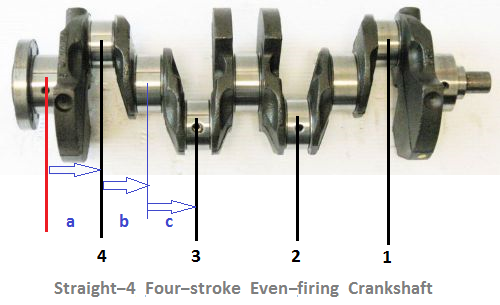
Suppose the angular twist of the crankshaft is defined as the angle of the crankpin of the 1st cylinder (the farthest cylinder from the flywheel) from the nearest to the flywheel crank journal.


Straight_4_Four_stroke_Even_firing_Crank


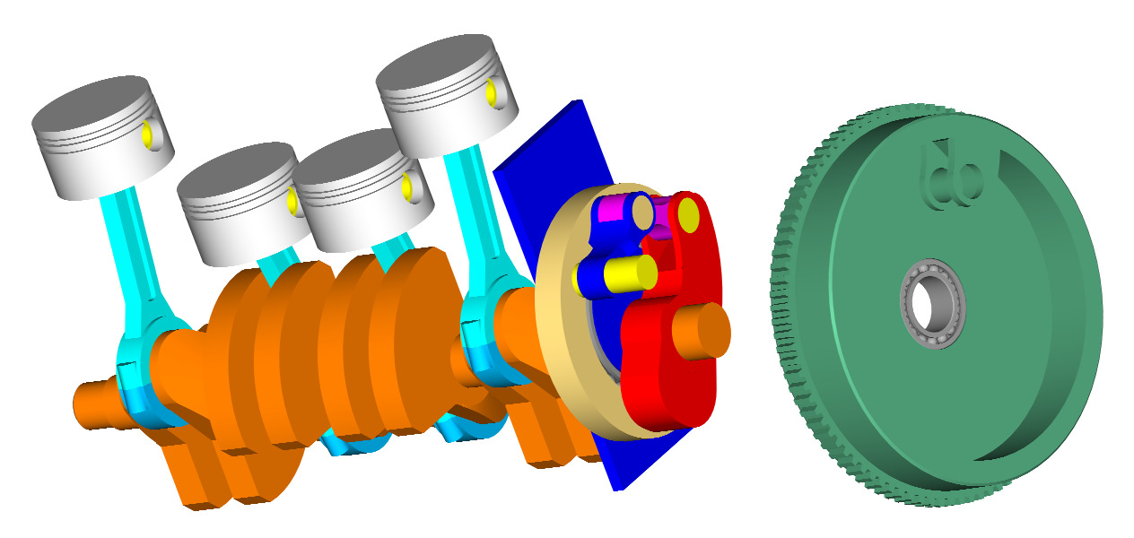
If the angular twist of the crankshaft is Δθ when the fourth cylinder burns / expands, then: when the third cylinder burns / expands the angular twist is 3*Δθ (because between the nearest to the flywheel crank journal and the crankpin of the third cylinder there are three crankshaft pieces like a: the a, the b and the c),

when the second cylinder burns / expands the angular twist is 5*Δθ (similar reasoning as before),

and when the first cylinder burns / expands the angular twist is 7*Δθ.


I.e. while the combustion pulses happen per 180 crank-degrees, the twisting of the crankshaft (measured at its complete length) maximizes once per 720 crank degrees and so it is of half order.


At low revs the inertia torque is small relative to the combustion pulses, so the PatVRA and the conventional load their crankshafts equally.

At high revs the inertia torque is the dominant load on the crankshaft of the conventional plane-crankshaft I-4, while the PatVRA is loaded only by the combustion torque pulses.


So, the PatVRA can use a thinner (i.e. having smaller diameter crankpins and main journals) crankshaft without spoiling reliability.


Among the advantages are:

the more lightweight – yet reliable – crankshaft,

the reduced friction (smaller diameter crankpin and journal bearings, no heavy idle loads reciprocating along the transmission),

the quieter / smoother operation (only useful torque passes to the transmission),

the springs on the clutch disk can be harder (or completely eliminated),

the better feeling (how well the drive wheels/tires are hooked up), etc.


I think the following quotes are useful for those who want to get the difference the PatVRA brings.

In simple words, it has the advantages of the cross-plane crankshaft (Yamaha R1), and all the advantages of the plane crankshaft, without their drawbacks.


The following quote is from https://www.motorcyc...crankshaft.html (October 2016) :


Here’s what Suzuki had to say in introducing the all-new GSX-R1000 last week, which uses the same 180-degree, or flat crank, it always has. Our lead photo shows the new GSX-R engine on the left and the outgoing one on the right; note that the baby bump on front of the old engine, where its small balance shaft used to live, is no more on the new engine.


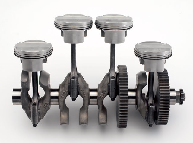
2005-bmw-k12s-t-10-zoom-633x469.jpg


Nearly all inline Fours use a flat crankshaft like this one (which doesn’t belong to the new GSX-R). Two pistons up + two pistons down = perfect primary balance.


“Suzuki engineers carefully considered using non-conventional, uneven-firing-order crankshaft phasing versus the GSX-R’s traditional even-firing-order crankshaft phasing.

“The theoretical advantages of uneven firing order can apply in MotoGP racing, where engine output exceeds 230 horsepower and the biggest obstacle to turning good lap times is cornering traction and the rider’s ability to feel how well the rear tire is hooked up at any given throttle opening. But there are very real inherent engineering challenges that must be overcome with an uneven firing order. It’s more difficult to produce strong power and torque with an uneven firing order, especially at low rpm and in the midrange. Vibration is increased, requiring much thicker and heavier crankcases and a counterbalancing shaft, and associated mechanical losses contribute to overheating.


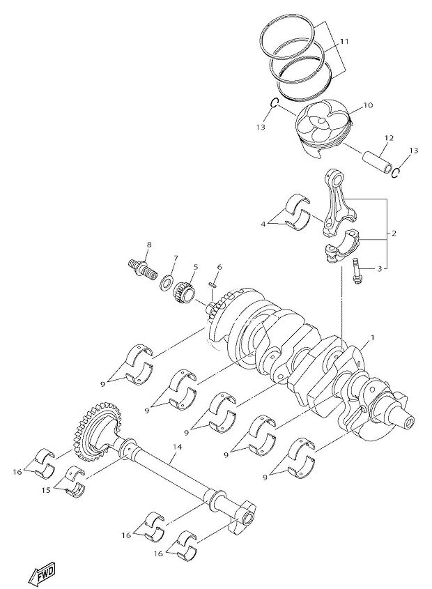
ya0415104009-464x633.gif


Yamaha’s Crossplane crank needs to spin this large balance shaft (part #14 on BikeBandit’s fiche) to quell its vibes; Suzuki’s new GSX-R1000 does away with the small balance shaft it used last year, joining other balance-shaft-free inline Fours like the BMW S1000RR, Honda CBR1000RR and others.


“The big question Suzuki engineers faced was whether or not, for a production motorcycle, the theoretical advantages of an uneven firing order design outweighed the inherent complications. Including the fact that solving the problem of making strong power with an uneven firing order while controlling vibration, heat and weight gain would make the motorcycle more expensive, significantly increasing the retail price.

“With testing, the engineers found that they could enhance traction and feel with a superb chassis design and effective electronics. And they decided that the even-firing-order, screamer engine sounded better, too.”

Ouch.

There you have it. We love the texture of the R1 big-bang engine and how it sounds, but time will tell if its added complexity eventually might go the way of the five-valve head.


An analysis of the “crossplane vs flat-crank” is at https://mecaniblog.wordpress.com/2016/08/06/crossplane-by-yamaha-a-technical-approach/ wherefrom the following plot is:


cptttt1.png?w=491


The torque delivery is smoother at the crossplane option, although the mean torque is the same for the two options (that means the same power). The main advantage of the crossplane configuration, is that deliverying the power more smoothly, the rear tire is able to stand more time in good conditions, and that is so important when we speak about racing.


Quote from https://www.motoroids.com/features/techspeak-crossplane-crankshaft/ :


motoroids_techspeak4.jpg


motoroids_techspeak10.jpg


The cure is a crankshaft with pistons at 90 degree intervals as opposed to 180 degrees of a flat-plane crankshaft and an irregular firing pattern. The inertia torque is reduced to almost zero before 10,000rpm and crucially, to only about 3% of the flat-plane crankshaft value at 15,000rpm. This means that the rear tyre will mimic the inputs of the throttle giving excellent feel which has been much appreciated and praised by riders all over the world.


SO WHAT’S THE DOWNSIDE?


Of course the law of physics state that you never get something for nothing and an irregular firing order means more vibrations that may require a balance shaft or heavier components to tame, thus losing you part of quick response that you have gained.


WHAT CAN BE BETTER THAN THE CROSS PLANE CRANKSHAFT?


Honda thinks it’s going to be the V4. In principle what the cross-plane crankshaft essentially does is that it mimics the working of a 90 degree V4 in the inline-4. But a V4 won’t be as compact as an inline 4, at least in theory with the bike losing out on shorter and therefore more nimble machine. Yamaha swear by their tech and will stick with inline-4. But you never know, Honda might just pull it off.


Thanks

Manolis Pattakos


#24 desmo

desmo
  • Tech Forum Host

  • 31,288 posts
  • Joined: January 00

Posted 13 October 2020 - 03:09

At this point, conventional motorcycle engines from the big makers are so incredibly developed and optimized that there are probably few and then only tiny real, empirical quantifiable gains left to be found. In such mature designs, engineering is pretty close to being an arm of marketing. All the low-hanging fruit was picked long ago. The huge upside of this is the product from all these makers is universally outstanding.


#25 gruntguru

gruntguru
  • Member

  • 7,683 posts
  • Joined: January 09

Posted 13 October 2020 - 03:32

Agreed. Although the focus of this invention - the inline four cylinder and inertia torque - is something that could well be enhanced in the motorcycle world. They have already spent a lot of time and money on this issue - playing with cross-plane cranks and the like.


#26 manolis

manolis
  • Member

  • 935 posts
  • Joined: May 03

Posted 13 October 2020 - 04:42

Hello Desmo and Gruntguru.


You write:


“At this point, conventional motorcycle engines from the big makers are so incredibly developed and optimized that there are probably few and then only tiny real, empirical quantifiable gains left to be found. In such mature designs, engineering is pretty close to being an arm of marketing. All the low-hanging fruit was picked long ago. The huge upside of this is the product from all these makers is universally outstanding.”


and


“Agreed. Although the focus of this invention - the inline four cylinder and inertia torque - is something that could well be enhanced in the motorcycle world. They have already spent a lot of time and money on this issue - playing with cross-plane cranks and the like.”


The real measure / evaluation of anything that seems “incredibly development and optimized” is when it competes with something else.


When they were compared side-by-side, the conventional design (plane crankshaft I-4) was defeated by the –then – unconventional design (cross-plane crankshaft).


The funny thing is that the Yamaha-R1 design was patented a few decades ago by Kawasaki. The “cross-plane crankshaft” project remained useless, until Yamaha made their R1 and became the permanent motoGP winner for several years.


The writers of the articles in the three quotes of my last post, explain that each of the two alternative “schools” we have today for the straight-four motorcycle engines (flat-plane crankshaft and cross-plane crankshaft) compromise with basic technical “issues”, having each one its own advantages and drawbacks.


If something can bridge the gap between the two “schools”, avoiding their drawbacks and combining their advantages, i.e.

the even firing,

the elimination of the inertia torque to the transmission,

the elimination of any external balance shaft(s),

the lightweight (of crankshaft and of the engine-casing),

the improved feeling of the rear tire “hooking”, etc,

then it is something .


Imagine a motoGP "flat crankshaft" motorcycle with the feeling of the Yamaha R1, and with Desmo-continuously-variable-valve-actuation ( DVVA at https://www.pattakon...ttakonDesmo.htm ) or PatRoVa rotary valves ( https://www.pattakon.com/pattakonPatRoVa.htm ) in the cylinder head for "unlimited" revs and flat torque.


Nobody can arhue that the modern engines (for motorcycles, cars etc) are “impressively developed and optimized”, however they can be even better and they have a long endless way for development and optimization.


Thanks

Manolis Pattakos


#27 manolis

manolis
  • Member

  • 935 posts
  • Joined: May 03

Posted 19 October 2020 - 16:49

Hello all.


Here:


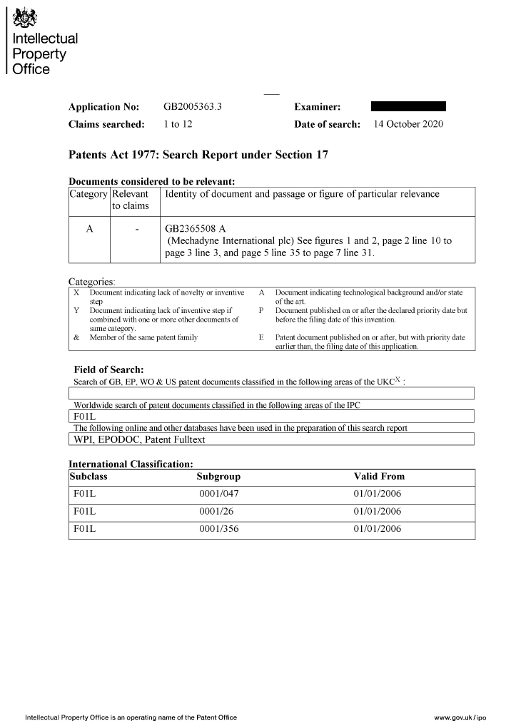
PatVVD_Search_Report.png


is the Search Report (prepared by the UK Patent Office; received today) for the PatVVD patent application:


PatVVD_5.png


The Search Report has only one document; it is the GB2365508A patent application filed by Mechadyne; and this document belongs in the A category (i.e. it is a “document indicating technical background and/or state of the art”).


So, according the Patent Examiner of the UK-IPO, the PatVVD invention is new and is not anticipated by any known prior art.


Here https://www.pattakon.../GB2365508A.pdf is the original document of the patent application of Mechadyne; at its last pages (21 to 24) you can see the Search Reports for Mechadyne’s invention.


Thanks

Manolis Pattakos


#28 Kelpiecross

Kelpiecross
  • Member

  • 1,730 posts
  • Joined: October 10

Posted 22 October 2020 - 06:38

 Interesting - it looks like Mechadyne is jumping on the eccentric variable camshaft drive band wagon.  But like all cams working on this principle it will soon rattle itself to bits.  I don't know if they claim to have enough duration increase to give throttle-free load control - it would be at the extreme of the range for this sort of cam arrangement.  And at this extreme range the eccentric drive mechanism is working all it joints/sliding bits frantically and wearing itself out.

 By contrast the Helical Cam can easily produce throttle-free effects.  Whether it is set at 250 or 400 (or whatever) degrees it doesn't "know"  (and probably doesn't care) - it makes no difference to the wear rate etc.


 I have always thought Mechadyne was an odd company - their variable cam designs are (to put it bluntly) crap.  An example is USPTO 10519821 - essentially a nightmare.  And yet despite turning out crap like this they stay in business and continue spending a fortune on patents etc.       


#29 manolis

manolis
  • Member

  • 935 posts
  • Joined: May 03

Posted 22 October 2020 - 17:24

Hello Kelpiecross.


You write:

“By contrast the Helical Cam can easily produce throttle-free effects.  Whether it is set at 250 or 400 (or whatever) degrees it doesn't "know"  (and probably doesn't care) - it makes no difference to the wear rate etc.”


This is the good range for the Helical Cam: throttle-free operation with the valves remaining open almost till the end of the compression stroke (light load operation), to allow most of the fresh mixture to exit from the cylinder and return back to the intake manifold.


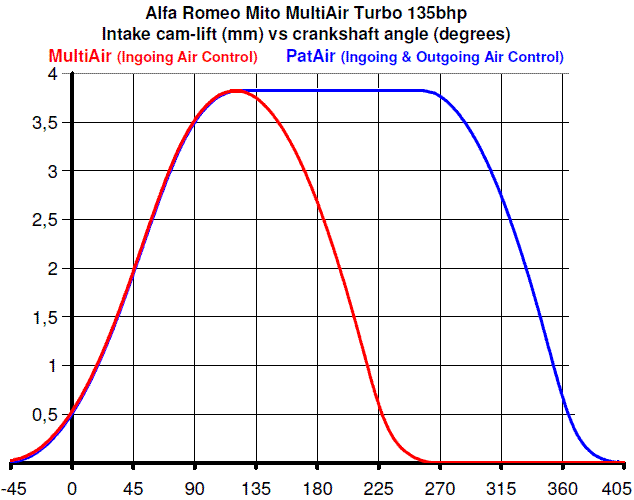
Say, like the PatAir:


mito_cam_lifts.gif


when it operates throttles in the “Outgoing Air Control” mode.


However the PatAir uses a single piece-crankshaft (the upper one)  :


Mito_Camshafts.jpg


having long-duration intake camlobes (like the right / blue one):


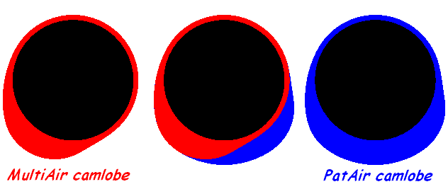
Mito_MultiAir_PatAir_camlobes.gif


Contrary to the Helical Cam, the PatAir can operate throttles  on “intake control” mode, too, closing the intake valves far before the BDC (actual duration from, say, 30 to 180+ degrees in this mode).


The control of the PatAir is “electronic” with feedback from a “high speed response” oxygen sensor (independent signal for each cylinder) allowing the independent alignment of the closing of the intake valves of each cylinder.


In comparison the Helical Cam has pure mechanical (or hydraulic, or ? . . .) control.


Regarding the wear of the Helical Cam, here is a video you posted in another discussion for the Helical Cam:


And here is what I replied:


Strictly technical thoughts and questions:


I suppose the HC needs a control mechanism (a linkage?) for the accurate (and lash free) axial displacement of the several rotating semi-cam-lobes of the Helical Camshaft.


Any photos of the control mechanism for a typical straight-four 16-valve engine modified to HC?


Is the control mechanical or hydraulic?

Is it simple and durable?

Are there any thrust-roller bearings between the sliding semi-cam-lobes and the control “linkage”?


In “your” video, the 3D-printed blue semi-cam-lobe seems as supported exclusively at one side (I mean the complete rings at its one end). Is this support adequate and durable?


Isn’t a problem the need for a minimum “constant lift region” (of some 40 crank degrees?)?


Isn’t a problem (friction, wear) that at high revs the “constant lift” portion of the cam-lobe is heavily loaded by the fully compressed valve springs? (with the valve immovable, there is no inertia to reduce the load from the valve spring).


In the HC it is required a fast deceleration on the valve just before the constant lift portion of the lobe, and a fast acceleration on the valve at the end of the constant lift portion of the cam lobe.

Doesn’t this mean that for the same rev limit, stiffer valve springs are necessary when an engine is modified to Helical Camshaft?


Can the HC with its trapezoidal valve lift profile rev at high rpm reliably?”


I.e., the Helicam Cam is neither lash-free, nor rattle-free. Its movable semi-cam-lobes are not well supported. It has both, anglular and axial lash / play. 


The VCC of Rover was reliable even at high revs. There are Rover and MG cars operating with this system for decades without problems.


The CVVD of Hyundai (actually a copy of the VCC) is in mass production and - reasonably  - has no reliability issues (Hyundai claims they have tested it for several years at all conditions).


In comparison to the VCC and CVVD: 
 
(quote from the PatVVD Patent Application) :


(the PatVVD)
avoids the sliding keys, the sliding key slots in pins and the sliding friction between cooperating / heavily loaded parts,
uses only constant length links pivotally or rotatably mounted,
for the support of the mechanism on a cylinder head it does not require bearings other than a set of coaxial bearings as those supporting a conventional camshaft on a cylinder head,
it does not require additional structure(s) to bear and displace the control parts,"
 

Thanks

Manolis Pattakos


Edited by manolis, 22 October 2020 - 17:40.


#30 Kelpiecross

Kelpiecross
  • Member

  • 1,730 posts
  • Joined: October 10

Posted 25 October 2020 - 05:16

 No lash, rattles or control linkage(?), thrust bearings etc.  - lobe segments are attached to 20mm inner shaft.   Lobe inserts ("semi-cam-lobes")  could hardly be better supported.  


 "Trapezoidal" profile nomenclature is your own - typically profile would resemble  US racing "lift limited" cam profiles.  


 The cam shown in the video has the correct geometry but doesn't  really reflect the proper HC construction - as the bloke (Matthew Hudson) says in the video. 


 The Rover VCC may have been reliable at high revs but did suffer significant long-term wear problems.


 When the HC is set at a particular duration there are no moving parts - it rotates as one piece - like a normal cam.  Whereas at a constant duration setting these eccentric drive abominations are constantly working their bits back and forth. 


 The HC just plain "works" and has been shown to give remarkable part-throttle fuel savings as well as the power increases you would expect with variable duration..               


#31 manolis

manolis
  • Member

  • 935 posts
  • Joined: May 03

Posted 26 October 2020 - 16:09

Hello Kelpiecross


Are there some drawings of the HC (Helical Cam / William's Cam) for a straight four-in-line to show ? With the complete control system included.


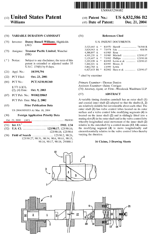
Here is the cover page of the William's Cam US6832586 patent:


William_Cam_US6832586.png


And here https://www.pattakon...m_US6832586.pdf is the complete US patent document


The mechanism shown has axial and angular lash.


By the way,every patent expires 20 years after the earliest priority.


The William's Cam patent has expired. 

Why all this secrecy?


Thanks

Manolis Pattakos


#32 Kelpiecross

Kelpiecross
  • Member

  • 1,730 posts
  • Joined: October 10

Posted 27 October 2020 - 11:33

 A few points:


The patent drawing is bloody dreadful. I am told it was only a sketch to guide the patent attorney's art department  in the final drawing - and yet they used it in the final patent. Well you can't expect too much for fifty thousand dollars. Even the words are a bit scrambled in parts - neither I or the HC mob has any idea who wrote them.


 One your point about lash etc. - the original GSX 250 variable cam has close tolerances (about one thou') on each side of the cam lobe inserts - when the cam is oily there is no "lash" - and only vaguely discernible when "dry".


 The big difference between the HC and the eccentric disasters  are that the sliding surfaces only move when the duration changes - not not constantly like the eccentric crap. The sliding/adjusting faces are vertical to each other and nitrided - they will last a million years (at least). 


  There has never been a four-cylinder HC.  The HC Co. considered that the GSX model totally proved the concept.  There were both earlier 4 and 6-cylinder  types made of a somewhat less complex arrangement (same construction, profile etc.) that even ran on the road for several months and proved the strength of the basic lobe insert concept.


  The only drawings that ever existed are those for the various components for the machinists  - no overall drawing.  It was built very much "by ear".   The next model (if there is one) will be a bit more "scientific" (hopefully).


 The HC Co. are well aware that the patent has run out - it never seemed to be of much use anyway.  This is illustrated by your  eccentric cam design and the increasingly numerous  cam arrangements on the same general  theme - none are worth a pinch of faecal matter patent-wise


 The HC Co.  is at the moment trying to stir up a bit of interest in the HC. They have apparently got some new ideas that are a follow-on  from the HC concept.  Like the HC itself one of the ideas in particular seems to have absolutely no "prior art" at all - and it may also be very useful for "ordinary" cams.


 Twenty years (or so) ago when the HC was being shown to various manufacturers etc. one of the persistent  general comments was that " as soon as we get 43 Volt  (why 43V, I wonder) electrical systems in cars mechanical cams will be a thing of the past, valves will be all solenoid-operated". Well it hasn't happened and doesn't look like happening - and the the HC remains the only genuine novel idea in the variable cam field - nothing else has appeared in the last twenty years.   


 As for "complete control systems" etc. - it is a trivial problem - the typical road car's cam phaser etc.  is all that would be needed.  The hydraulic cylinder doesn't need to be re-invented.      


.        


Edited by Kelpiecross, 27 October 2020 - 11:37.


#33 gruntguru

gruntguru
  • Member

  • 7,683 posts
  • Joined: January 09

Posted 27 October 2020 - 21:02

Twenty years (or so) ago when the HC was being shown to various manufacturers etc. one of the persistent  general comments was that " as soon as we get 43 Volt  (why 43V, I wonder) electrical systems in cars mechanical cams will be a thing of the past, valves will be all solenoid-operated". Well it hasn't happened and doesn't look like happening - and the the HC remains the only genuine novel idea in the variable cam field - nothing else has appeared in the last twenty years.           

42 volts was the proposed standard - 3 x 12v batteries. Why not 36v? 12v is a nominal voltage for a 6 cell lead acid - approximate resting voltage of a charged battery. As you know the system runs at closer to 14v with the alternator charging. I guess they split the difference - 42v is probably a better reference for specifying accessories to operate in such a system.


Koenigsegg's Freevalve system is more "novel" and has far greater potential and versatility than the HC - and is already in production (in a very low volume car).


#34 Kelpiecross

Kelpiecross
  • Member

  • 1,730 posts
  • Joined: October 10

Posted 05 November 2020 - 03:18

42 volts was the proposed standard - 3 x 12v batteries. Why not 36v? 12v is a nominal voltage for a 6 cell lead acid - approximate resting voltage of a charged battery. As you know the system runs at closer to 14v with the alternator charging. I guess they split the difference - 42v is probably a better reference for specifying accessories to operate in such a system.


Koenigsegg's Freevalve system is more "novel" and has far greater potential and versatility than the HC - and is already in production (in a very low volume car).


  I was going to write a very long and very clever  criticism of the Freevalve system - but I think this video says it all - it's crap, and it's not really  a new idea.  The HC may not be perfect and "all-singing/all dancing"  but it can do a lot and it's simple - basically an a camshaft with adjustable duration.  If the HC control system fails it reverts to being a "normal" camshaft.  


https://www.bing.com...etail&FORM=VIRE


#35 gruntguru

gruntguru
  • Member

  • 7,683 posts
  • Joined: January 09

Posted 05 November 2020 - 21:08

. . . . . it's not really  a new idea. 

Opening and closing the valves on an electrical signal is a very old idea - almost as old as the IC engine. Inventors have been trying to do it for a hundred years. (Same goes for VVD by "dwelling" the valve at peak lift.)


https://www.bing.com...33&&FORM=VDRVRV


#36 manolis

manolis
  • Member

  • 935 posts
  • Joined: May 03

Posted 06 November 2020 - 06:06

Hello all.


Here is the Desmodromic system used in the old Ducati Modial 175 (more at https://www.desmodro...-b-mondial-175/ )


Mondialdrawingsmall.jpg?ssl=1


Here is the above system animated:


 MondialDesmoMono3.gif?ssl=1


The blue “cam follower” at top is secured to the brown parts whereon the valve is also secured.


The crankshaft has two “complementary” cam lobes: one for the opening of the valve, the other for the closing of the valve.


Suppose the cam is decelerated during a period of its rotation and accelerated during another period of its rotation.


How?


With a PatVVD system mounted at the end of the camshaft; say, like:


PatVVD_Control_Lever.gif


Turning (and keeping) the cyan lever at an angle the opening valve duration increases; turning (and keeping) the cyan lever at another angle the opening valve duration decreases.


The opening and closing cam lobes continue being complementary.


The system continues being Desmodromic (which means: the valve opens positively AND closes positively without the need of restoring valve springs).


Think the PatVVD system disposed between the gearwheel at the end of the camshaft and the camshaft  of a modern Desmodromic engine:


Ducati_Panigale_valve_train.jpg


and you have an impressive application of the PatVVD: the Desmodromic engine can run at an infinity of modes, from eco-friendly (say with zero overlap and short valve opening duration), to normal Desmodromic (say, as it runs now), to racing (extreme overlap and duration).


The required control is simple: rotation of the cyan lever at another angle; for each angle of the cyan lever, a different mode (or valve duration) is selected.


The simplest / cheapest control is the manual one (the ECU receives a signal for the new valve duration to adjust the injection and ignition).


Another way is a servomotor (controlled by the ECU) to turn the cyan lever, with the ECU adjusting the injection and ignition tables.


As for the durability of the system, the same mechanism (PatVRA, more at https://www.pattakon...pattakonVRA.htm ) can be used to filter the inertia torque, liberating the gearbox from idle loads, friction and wear, and providing better felling to the driver.


Thanks

Manolis Pattakos


Edited by manolis, 06 November 2020 - 06:11.


#37 Kelpiecross

Kelpiecross
  • Member

  • 1,730 posts
  • Joined: October 10

Posted 07 November 2020 - 05:41

  Eccentric drive and desmodromic?  plus possibly the crankshaft eccentric drive? -  impossibly complex/complicated  for very little (if any) return benefits.    The mechanical equivalent of the Freevalve.        


#38 manolis

manolis
  • Member

  • 935 posts
  • Joined: May 03

Posted 07 November 2020 - 08:18

Hello Kelpiecross.


You write:

" Eccentric drive and desmodromic?  plus possibly the crankshaft eccentric drive? -  impossibly complex/complicated  for very little (if any) return benefits.    The mechanical equivalent of the Freevalve."


Are you sure you understand how the PatVVD works?


What is the “crankshaft eccentric drive”?


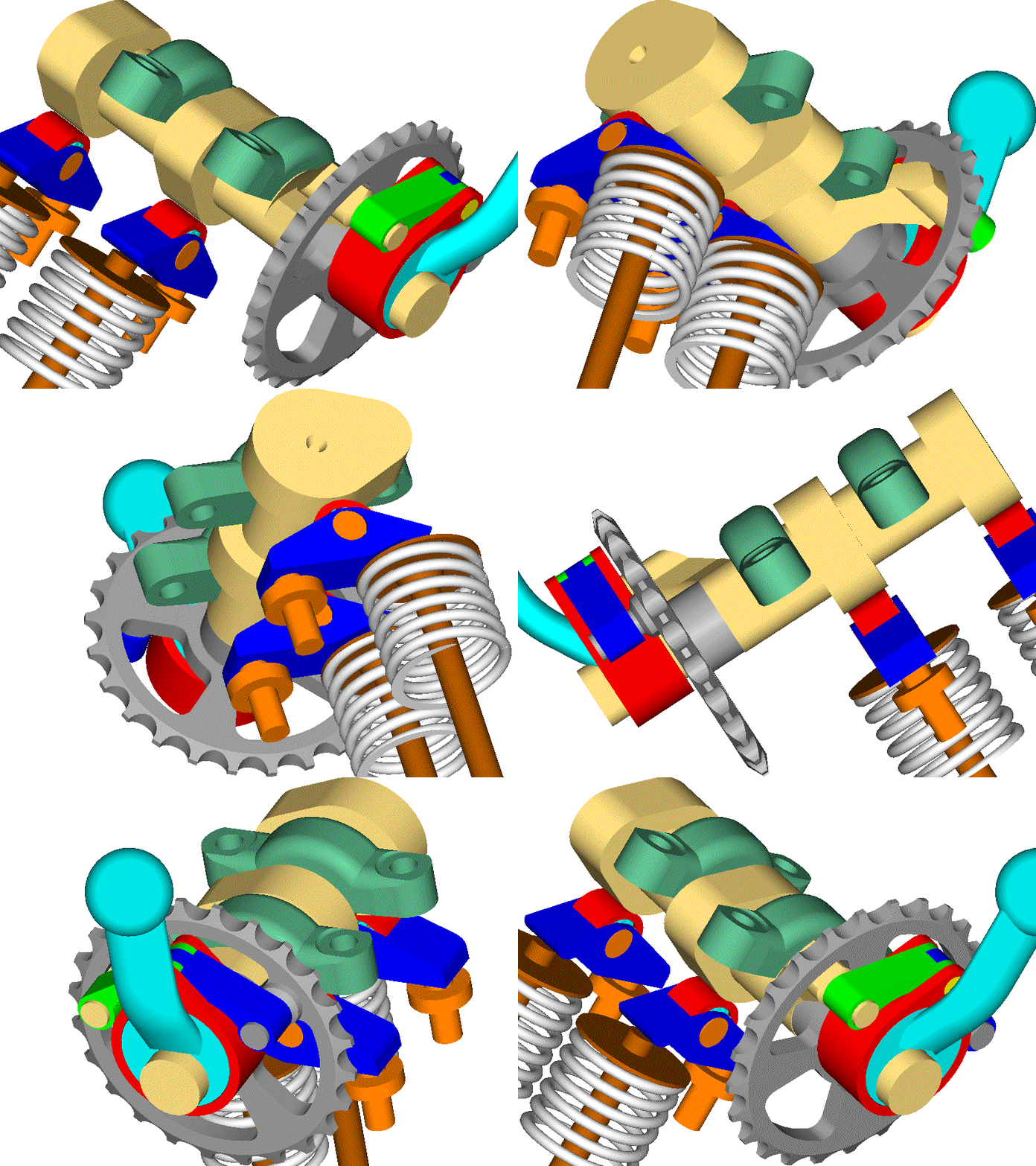
The only you add to the conventional Desmodromic system is a simple linkage between the sprocket (or gearwheel) at the one end of the camshaft and the camshaft; this linkage varies the angular speed of the camshaft during one complete rotation.


The following animation is for a non-Desmodromic cylinder head:


PatVVD_1.gif      


however the VVD mechanism for a Desmodromic cylinder head is exactly the same as above (only the camshaft changes: besides the normal (or opening) cam lobes, it requires closing cam lobes, too).


The above VVD mechanism comprises:


the cyan control lever, which is rotatably mounted on the one end of the (beige) camshaft; note: the control lever moves (actually turns for a few degrees) only when a different valve opening duration is required,


the red ring which is rotatably mounted on the cyan control lever,


and the green and red small rods: the green one is connecting the red ring with the (beige) camshaft, the blue one is connecting the red ring with the (grey) sprocket (or gearwheel).


The three moving parts are simple, small, well supported, strong (for the loads they bear) and easy to make (I can't think an easier and cheaper modification for a conventional (say, a CRF450) or a Desmodromic cylinder head).


With one such mechanism per cylinder head, the Desmodromic Ducati Panigale V-2  


(worth to note here: despite it is one of the most advanced engines today, it has one and only mode of operation, i.e. it uses the same valve lift profile at all conditions of operation, from idling to the red line)


can operate at an infinity of different modes (economy mode, normal mode, racing mode etc); all it takes is the rotation of the cyan levers for a few degrees in order a different valve opening duration to be selected.


Worth to note (again): the rest Ducati Panigale engine (including the desmodromic camshafts and the opening and closing rocker arms) remains unchanged.


For the valves the rotation at variable-speed of the existing Desmodromic camshafts is OK. More than OK, because at the longer valve durations (i.e. at the higher revs where the longer valve durations are useful) the acceleration and jerk reduces relative to those of the conventional Desmodromic system wherein the camshafts rotate at constant angular velocity during a complete rotation.


In the previous it was described the simple / cheap / easy modification of the state-of-the-art single-mode Desmodromic systems to the infinite-modes PatVVD-Desmordomic systems.


HC


It is not important that the HC cannot fit with a Desmodromic systems.


What is important is the actual (the real) complication the HC brings and its side-effects / limitations (like the minimum required valve duration, the need for a 30-40 degrees constant lift on the noses of the cam lobes, the increased acceleration and jerk, the need for “perfect fit” of the curves whereon the half cam-lobes move and are hold / driven, etc).


As for the complete control system of the HC for a straight four engine, it seems that despite its patents have expired, it is a top secret. 


Thanks

Manolis Pattakos